Charged-Particle Source and Method for Cleaning a Charged-Particle Source Using Back-Sputtering

a technology of charged particles and back-sputtering, which is applied in the direction of basic electric elements, electric discharge tubes, electrical equipment, etc., can solve the problems that the cleaning procedure as known from the state of the art cannot be effective against the accumulation of contamination factors during mounting, and achieve the effect of not disassembling the optical system

Active Publication Date: 2019-08-01
IMS NANOFABTION
View PDF7 Cites 7 Cited by
  • Summary
  • Abstract
  • Description
  • Claims
  • Application Information

AI Technical Summary

Benefits of technology

[0022]This solution offers an efficient implementation of cleaning in a charged-particle source. It also provides an efficient tool for generating, extracting and / or controlling the trajectory of the charged particles present in the source environment. The ionized gas particles are directed onto the emitter surface for removing material from the surface, for instance by sputtering (back-sputtering) and / or etching effects. In a cleaning mode, the ionization of the gas species in the source space is partially or entirely decoupled from the primary beam radiation as produced by the emitter surface. In the mentioned first cleaning mode (also referred to as ‘soft cleaning mode’), the ionization is enhanced by secondary electrons emitted at the counter electrodes and possibly other components surrounding the source space (such as the adjustment electrodes discussed further below) as a consequence of being hit by the particles of the primary beam radiation.
[0023]Thus, the invention offers a larger degree of freedom concerning the parameters of operation of the source during a cleaning process, and allows to better adjust the energy of the ionizing radiation so as to achieve a desired cleaning result, the preferential location within the source space where the ionization takes place and ultimately the ionization rate of the gas species present in the source space to operating parameters suitable to achieve efficient cleaning of the emitter surface. Thus, controlling the sputtering rate at the emitter surface is improved. The ionization rate can be adjusted based on, e.g., the binary-encounter dipole model presented in the article “Binary-encounter-dipole model for electron-impact ionization” of Y.-K. Kim & M. E. Rudd, Phys. Rev. A 50, 3954 (1994). The source setup of the invention allows an improved control of trajectories of the charged particle present in the source space, including those species which are unintentionally present, such as residual gas from the environment.
[0033]In order to further improve the cleaning processes and enable a better control of the locations to be cleaned, it may be advantageous when at least two of the adjustment electrodes are realized as split electrodes, each of said split electrodes being composed of at least two, preferably four, sectorial electrodes, which sectorial electrodes are configured to be applied different electrostatic potentials. In addition, these split electrodes may be used during a cleaning mode for directing ionized particles to specific regions on the emitter surface. Alternatively or in combination, the split electrodes may be configured to tune the intensity of ionized particles impinging on the emitter surface by means of the electrostatic potentials of the counter electrode and the adjustment electrodes including the split electrodes.

Problems solved by technology

Thus, the cleaning procedure as known from the state of the art would not be effective against contamination factors accumulated during mounting or during operation.

Method used


Image

  • Charged-Particle Source and Method for Cleaning a Charged-Particle Source Using Back-Sputtering
  • Charged-Particle Source and Method for Cleaning a Charged-Particle Source Using Back-Sputtering
  • Charged-Particle Source and Method for Cleaning a Charged-Particle Source Using Back-Sputtering

Examples


Embodiment Construction

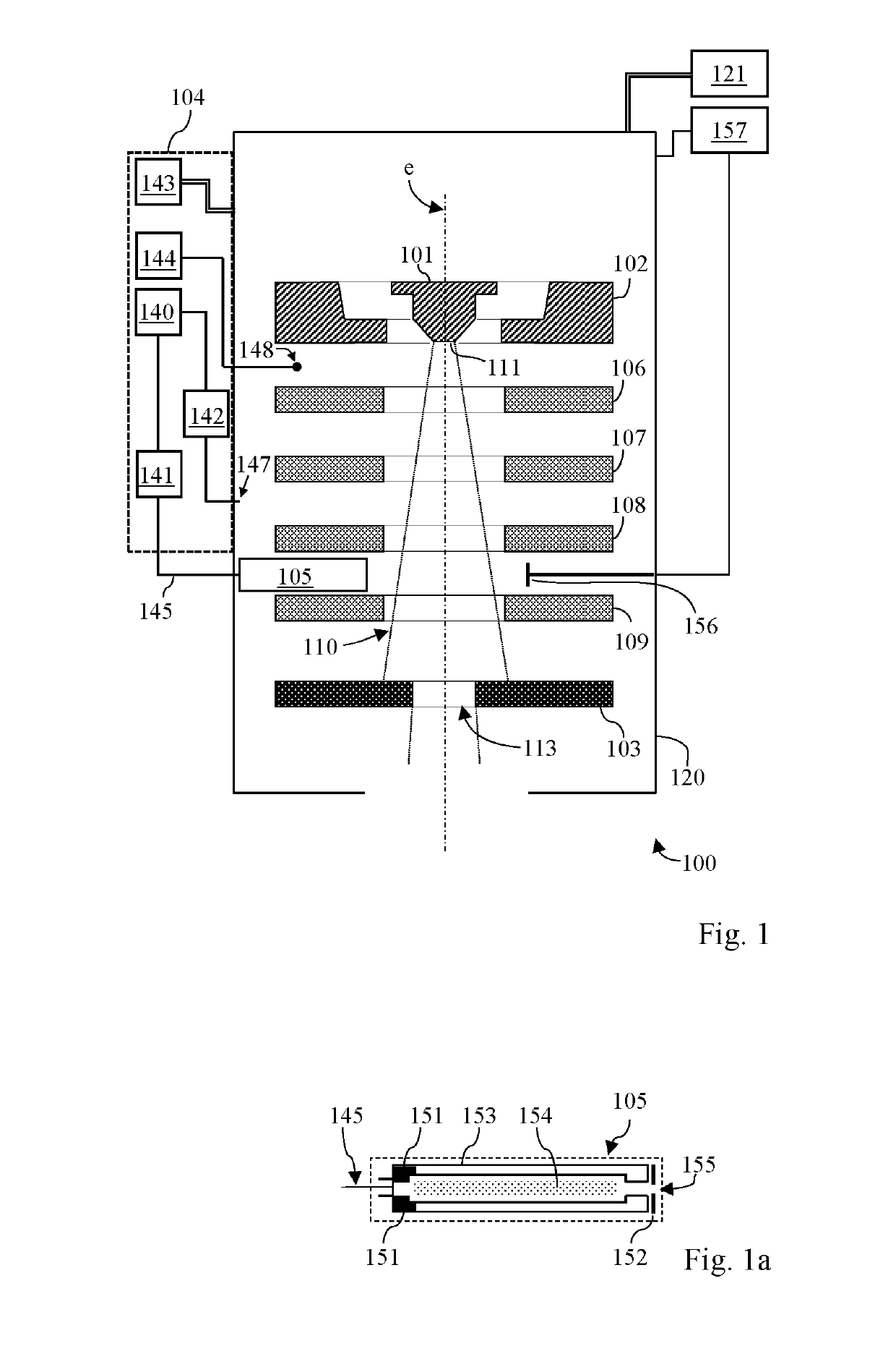
[0053]The detailed discussion of exemplary embodiments of the invention given below discloses the basic concepts and further advantageous developments of the invention. The embodiments refer to an electron source, but also elucidate methods using this source to generate charged particle beams with uniform current density and to condition the cathode surface by means of physical sputtering and / or chemical etching during a maintenance procedure. It will be evident to the person skilled in the art to freely combine several or all of the embodiments discussed here as deemed suitable for a specific application of the invention. Throughout this disclosure, terms like “for instance”, “advantageous”, “exemplary” or “preferred” indicate elements or dimensions which are particularly suitable (but not essential) to the invention or an embodiment thereof, and may be modified wherever deemed suitable by the skilled person, except where expressly required. It will be appreciated that the inventio...


PUM


Abstract

A charged-particle source for emission of electrons or other electrically charged particles comprises, located between the emitter electrode having an emitter surface and a counter electrode, at least two adjustment electrodes; a pressure regulator device is configured to control the gas pressure in the source space at a pre-defined pressure value. In a first cleaning mode of the particle source, applying a voltage between the emitter and counter electrodes directs gas particles towards the counter electrode, generating secondary electrons which ionize particles of the gas in the source space, and electrostatic potentials are applied to at least some of the adjustment electrodes, generating an electric field directing the ionized gas particles onto the emitter surface.

Description

CROSS REFERENCE TO RELATED APPLICATIONS[0001]This application claims priority to U.S. Provisional Application No. 62 / 623,952, entitled “Charged-Particle Source and Method For Cleaning a Charged-Particle Source Using Back-Sputtering” to Platzgummer et al., filed Jan. 30, 2018, the disclosure of which is incorporated by reference herein in its entirety.FIELD OF THE INVENTION[0002]The present invention relates to a charged-particle source which is suitable for use in, or as part of charged-particle nano-pattering or inspection tools, in particular of the multi-beam type. More specifically, the invention relates to a source for emission of electrically charged particles, in particular electrons, as a charged-particle beam along a direction of emission, with the charged-particle source comprising[0003]a housing connectable to a vacuum system, allowing the charged-particle source being operated at a high vacuum,[0004]an emitter electrode (i.e., an emitter anode or cathode, depending on wh...

Claims


Application Information

Patent Timeline
Patent Type & Authority Applications(United States)
IPC IPC(8): H01J37/063H01J37/305H01J37/065H01J37/147H01J37/30
CPCH01J37/063H01J37/3056H01J37/065H01J37/1477H01J37/3007H01J2237/06375H01J2237/022H01J37/3177
Inventor PLATZGUMMER, ELMARCAPRIOTTI, MATTIASPENGLER, CHRISTOPH
Owner IMS NANOFABTION
Why Eureka
Try Eureka