Method and apparatus for selectively severing and analyzing non-covalent and other bonds of biological macromolecules

a technology of biological macromolecules and non-covalent bonds, applied in the field of selective severing and analyzing non-covalent bonds and other bonds of biological macromolecules, can solve the problems of difficult quantitative analysis of the strength of the interaction accurately using the ordinary esi-collision activation method, and the solution of the biological sample unavoidably contains a surface-active agen

Active Publication Date: 2009-03-19
UNIVERSITY OF YAMANASHI
View PDF0 Cites 7 Cited by
  • Summary
  • Abstract
  • Description
  • Claims
  • Application Information

AI Technical Summary

Benefits of technology

[0018]Preferably, the biological sample is subjected to temperature control such as heating and cooling as necessary. Cooling makes it possible to handle a complex consisting of bonds that are very weak and difficult to measure under ordinary temperatures (e.g., room temperature).

Problems solved by technology

However, in a case where electrostatic-interactions and hydrogen bonding are the prime causes of formation of the complex and the structure of the constituent molecules is not sufficiently stable, as in the case of a complex comprising double-stranded DNA and protein, there are instances where not only the non-covalent bonds but also weak covalent bonds are broken and measured together with these fragments if the above-described method is applied.
Consequently, the spectra obtained are complicated and it is difficult to quantitatively analyze the strength of the interaction accurately using the ordinary ESI-collision activation method.
One other problem in the ion analysis of biological macromolecules is that there are cases where the solution of the biological sample unavoidably contains a surface-active agent.
If the solution of the biological sample contains a surface-active agent, it will be difficult to vaporize and ionize the protein with the ESI method.

Method used


Image

  • Method and apparatus for selectively severing and analyzing non-covalent and other bonds of biological macromolecules
  • Method and apparatus for selectively severing and analyzing non-covalent and other bonds of biological macromolecules
  • Method and apparatus for selectively severing and analyzing non-covalent and other bonds of biological macromolecules

Examples


first embodiment

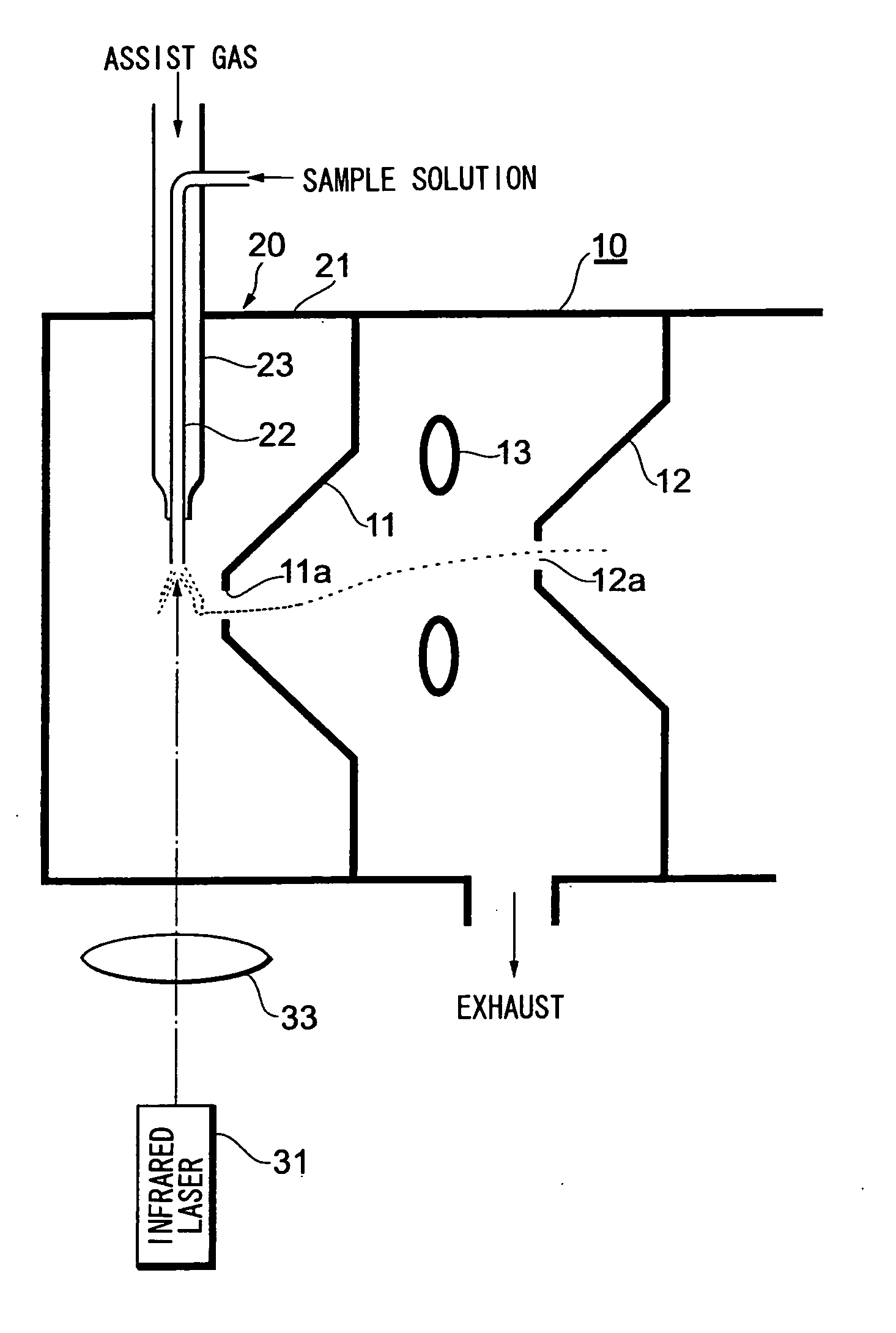
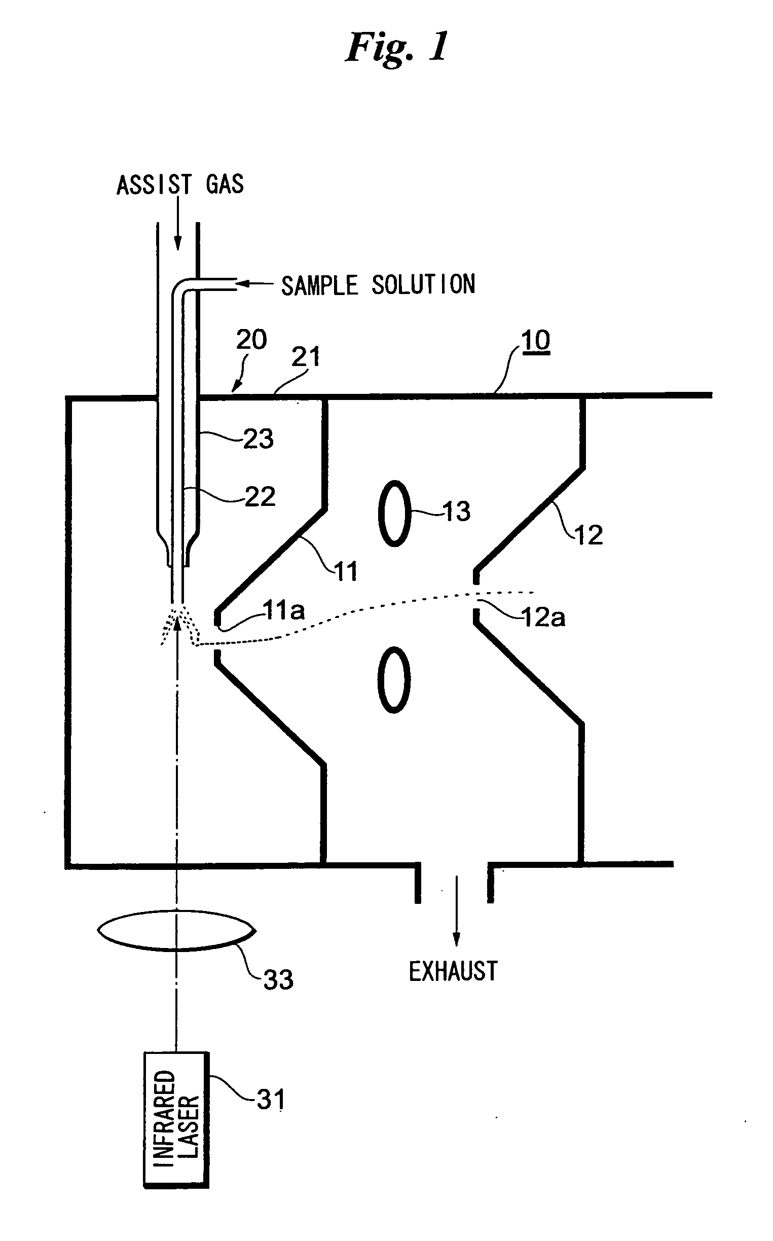
[0032]FIG. 1 illustrates the overall structure of an analyzing apparatus that includes a laser spray apparatus attached to a mass analyzer in the vicinity of an ion introduction port thereof.

[0033]A first orifice 11 provided with a miniscule hole 11a is attached to a mass analyzer 10 at the ion introduction port thereof. The miniscule hole 11a serves as the ion introduction port. The interior of the mass analyzer 10 is held in vacuum. A second orifice 12 provided with a miniscule hole 12a is provided deeper within the mass analyzer 10. A ring lens 13 is provided between the first orifice 11 and second orifice 12. Ions produced by a laser spray apparatus 20 pass through the miniscule hole 11a of the first orifice 11, are deflected by the lens 13, pass through the miniscule hole 12a of the second orifice 12 and are introduced to the interior of the mass analyzer 10.

[0034]A housing 21 of the laser spray apparatus 20 is attached to the vessel wall of the mass analyzer 10 so as to surrou...

second embodiment

[0052]FIG. 6 is a structural view of an analyzing apparatus according to a second embodiment. Components in FIG. 6 identical with those shown in FIG. 1 are designated by like reference characters and need not be described again.

[0053]In addition to the first outer tube 23, a second outer tube 24 is provided outside the capillary 22 at the tip of the capillary 22 and spaced away from the first outer tube 23. The ends of both outer tubes 23, 24 have slender tips providing with openings in the vicinity of the tip of capillary 22.

[0054]In this embodiment, a temperature adjusting device 40 is equipped with a tank 41 of liquid nitrogen. Vaporized nitrogen gas is fed from the tank 41 to a supply tube 42. The supply tube 42 branches into two branch tubes 43, 44. The branch tubes 43, 44 are connected to the outer tubes 23, 24. The branch tubes 43, 44 are provided with flowrate regulating valves 45, 46 and heaters 47, 48, respectively, which are capable of being operated and controlled indepe...

third embodiment

[0064]FIG. 7 illustrates a nano-laser spray apparatus.

[0065]A capillary 22A is formed from glass so as to be extremely slender, and the inner diameter of the capillary tip is on the order of 1 to 10 μm. A very small amount of the sample solution is placed in the capillary 22A and the base end thereof is closed by a plug 22a.

[0066]A metal wire (a conductor wire, typically a platinum wire) 70 is passed through the plug 22a and inserted into the capillary 22A from the base end of the capillary 22A. It will suffice if the metal wire 70 is inserted up to the vicinity of the middle of the capillary 22A along the length direction thereof. A high voltage is applied to the metal wire 70 by a high-voltage generator 71. If the metal wire 70 and sample solution within the capillary 22A are in contact, the high voltage will be applied up to the tip of the capillary through the electrically conductive sample solution. It may be so arranged that instead of inserting a metal wire, a metal membrane...


PUM

PropertyMeasurementUnit
wavelengthaaaaaaaaaa
diameteraaaaaaaaaa
diameteraaaaaaaaaa

Abstract

A biological sample solution is ionized by electrospray and the sample solution is irradiated with an infrared laser beam to dissociate biological macromolecules into the constituents thereof. As a result, only non-covalent bonds of the biological macromolecules can be selectively severed and analyzed.

Description

TECHNICAL FIELD[0001]This invention relates to a method and apparatus for selectively severing and analyzing non-covalent bond and other bonds of biological macromolecules.BACKGROUND ART[0002]In ion analyzing equipment such as a mass analyzer, it is necessary to ionize the sample that is to be analyzed. Accordingly, an ionization apparatus is provided as a preliminary stage of these ion analyzers.[0003]The electrospray ionization (ESI) method is available as one ionization method used in an ion analyzer.[0004]The electrospray ionization (ESI) method is in wide use as one method that has the ability to ionize biological macromolecules such as DNA and proteins. With the ESI method, DNA and proteins can be ionized gently and complexes comprising multiple DNA or proteins formed by non-covalent bonding also can be ionized as is. In view of this feature, the ESI method is being used in structural functional analysis of biological molecules.[0005]Biological activity is governed by the inte...

Claims


Application Information

Patent Timeline
Patent Type & Authority Applications(United States)
IPC IPC(8): B01J19/12B01D57/02G01N1/28G01N1/44G01N27/62G01N33/48H01J49/16
CPCG01N1/44H01J49/0059Y10T436/24H01J49/165H01J49/161
Inventor TAKAMIZAWA, ATSUSHIJAN ARNE, SUNNER
Owner UNIVERSITY OF YAMANASHI
Why Eureka
Try Eureka