[0006]P-waves usually have much lower amplitude than S-waves. The large difference in signal amplitude makes the detection and measurement of P-waves more difficult. The problem is worse for logging while drilling (LWD) because of the interference of waves propagating along the tool. For wireline tools, acoustic isolators can be designed that almost completely block the tool wave so that there is little contamination of the formation arrival by the tool signal. See, for example, U.S. Pat. No. 5,229,553 to Lester. However, for an MWD tool, the mechanical strength constraints limit the performance of the acoustic isolator. Examples of acoustic isolators for LWD are shown, for example, U.S. Pat. No. 6,082,484 to Molz et al., in U.S. Pat. No. 6,615,949 to Egerev et al., U.S. Pat. No. 6,820,716 to Redding et al., U.S. Pat. No. 6,915,875 to Dubinsky et al., U.S. Pat. No. 7,028,806 to Dubinsky et al., and U.S. Pat. No. 7,032,707 to Egerev et al all having the same assignee as the present disclosure. See also U.S. Pat. No. 7,216,737 to Sugiyama, U.S. Pat. No. 5,639,997 to Mallett.
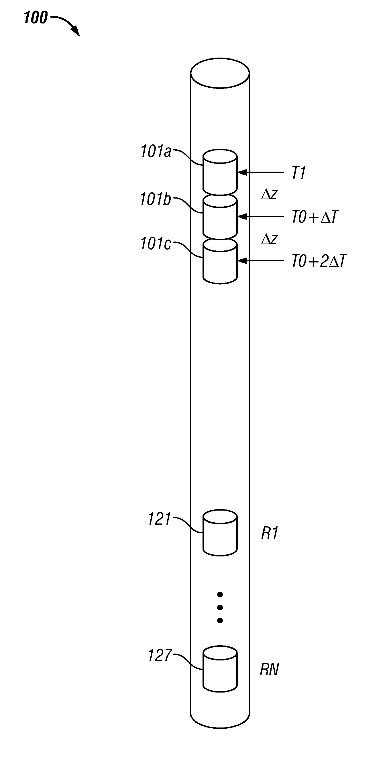
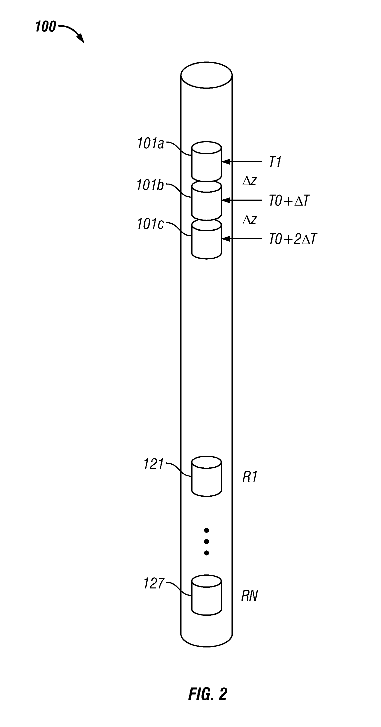
[0007]One embodiment of the disclosure is an apparatus for logging an earth formation. The apparatus includes a logging tool having at least one transmitter which includes a plurality of segments. The logging tool is configured to be conveyed in a borehole and generate an acoustic wave in the formation. At least one receiver is configured to produce a signal responsive to the generated acoustic wave. The apparatus further includes a processor configured to activate the plurality of segments using a time delay which accentuates an axially propagating compressional wave in the formation, determine from the signal a compressional wave velocity of the formation, and record the determined compressional wave velocity on a suitable medium. The at least one receiver may include a plurality of spaced-apart receivers forming a receiver array. The processor may further be configured to determine the time delay based at least in part on an estimated compressional wave velocity and a spacing between the segments of the at least one transmitter. The processor may further be configured to improve the determined compressional wave velocity using redundancy in signals received by the plurality of receivers. The processor may be further configured to estimate a shear wave velocity of the formation. The logging tool may be part of a downhole assembly conveyed on a drilling tubular or a wireline.
[0008]Another embodiment of the disclosure is a method of logging an earth formation. The method includes conveying at least one transmitter having a plurality of segments into a borehole, sequentially activating the plurality of segments using a time delay which accentuates a compressional wave component of a generated acoustic wave in the formation, using at least one receiver to produce a signal responsive to be generated acoustic wave, determining from the signal a compressional wave velocity of the formation, and recording the determined compressional wave velocity on a suitable medium. The method may include using for the at least one receiver a plurality of spaced apart receivers forming a receiver array. The time delay may be determined based at least in part on an estimated compressional wave velocity and a spacing between the segments of the at least one transmitter. The method may further include improving the determined compressional wave velocity using information redundancy in signals received by the plurality of receivers. The method may further include estimating a shear wave velocity of the formation.
[0009]Another embodiment of the disclosure is an apparatus for logging an earth formation. The apparatus includes a logging tool configured to be conveyed in a borehole. At least one transmitter on the logging tool is configured to generate an acoustic wave in the formation. The apparatus further includes at least one receiver including a plurality of segments, each of the segments configured to produce a signal in response to the generated acoustic wave. The apparatus also includes a processor configured to combine the signals from the plurality of segments using a time delay which accentuates an axially propagating compressional wave in the formation, determine from the combined signal a compressional wave velocity of the formation, and record the determined compressional wave velocity on a suitable medium. The at least one receiver may further comprise a plurality of spaced apart receivers forming a receiver array. The processor may be further configured to determine the time delay based at least in part on an estimated compressional wave velocity and a spacing between the segments of the at least one receiver. The processor may be further configured to improve the determined compressional wave velocity using information redundancy in signals by the plurality of receivers. The processor may be further configured to estimate a shear wave velocity of the formation. The logging tool may be part of a downhole assembly conveyed on a drilling tubular or a wireline.
[0010]Another embodiment of the disclosure is a method of logging an earth formation. The method includes conveying at least one transmitter into a borehole and generating an acoustic wave. Each of a plurality of segments of at least one receiver is used to produce a signal responsive to the generated acoustic wave. The signals from the plurality of segments are combined using a time delay which accentuates an axially propagating compressional wave in the formation. A compressional wave velocity of the formation is determined from the combined signal and recorded on a suitable medium. A plurality of receivers forming a receiver array may be used for the at least one receiver. The time delay may be determined based at least in part on an estimated compressional wave velocity and a spacing between the segments of the at least one receiver. The determined compressional wave velocity may be improved by using information redundancy in signals generated by the plurality of receivers. The method may further include estimating a shear wave velocity of the formation.

