Flying device

Active Publication Date: 2019-08-08
PANASONIC INTELLECTUAL PROPERTY MANAGEMENT CO LTD
View PDF0 Cites 10 Cited by
  • Summary
  • Abstract
  • Description
  • Claims
  • Application Information

AI Technical Summary

Benefits of technology

[0014]As described above, the present invention provides a flying device equipped with an inner-rotor-typ

Problems solved by technology

The outer-rotor-type motor of the non-closed structure, on the other hand, is inferior to the inner-rotor-type motor of the closed structure in dust-proofness that prevents deposition of foreign matter, such as dust.
When the flying device having the motor element serving as the driving source for the rotary vanes is used in the agricultural field, the flying device has problems caused by a scattered mist of a chemical, such as an agricultural chemical, entering the motor element and depositing there or flying or floating dust or the like entering the motor element.
When the small flying device is used in a coastal area or an area in which the flying device sprays a sn

Method used


Image

  • Flying device
  • Flying device
  • Flying device

Examples


Embodiment Construction

[0020]An exemplary embodiment of the present invention will hereinafter be described with reference to the drawings. As an example of this exemplary embodiment, a flying device equipped with an inner-rotor-type motor element superior in dust-proofness and reduced in weight will be described. The present invention is not limited by the exemplary embodiment to be described below.

Exemplary Embodiment

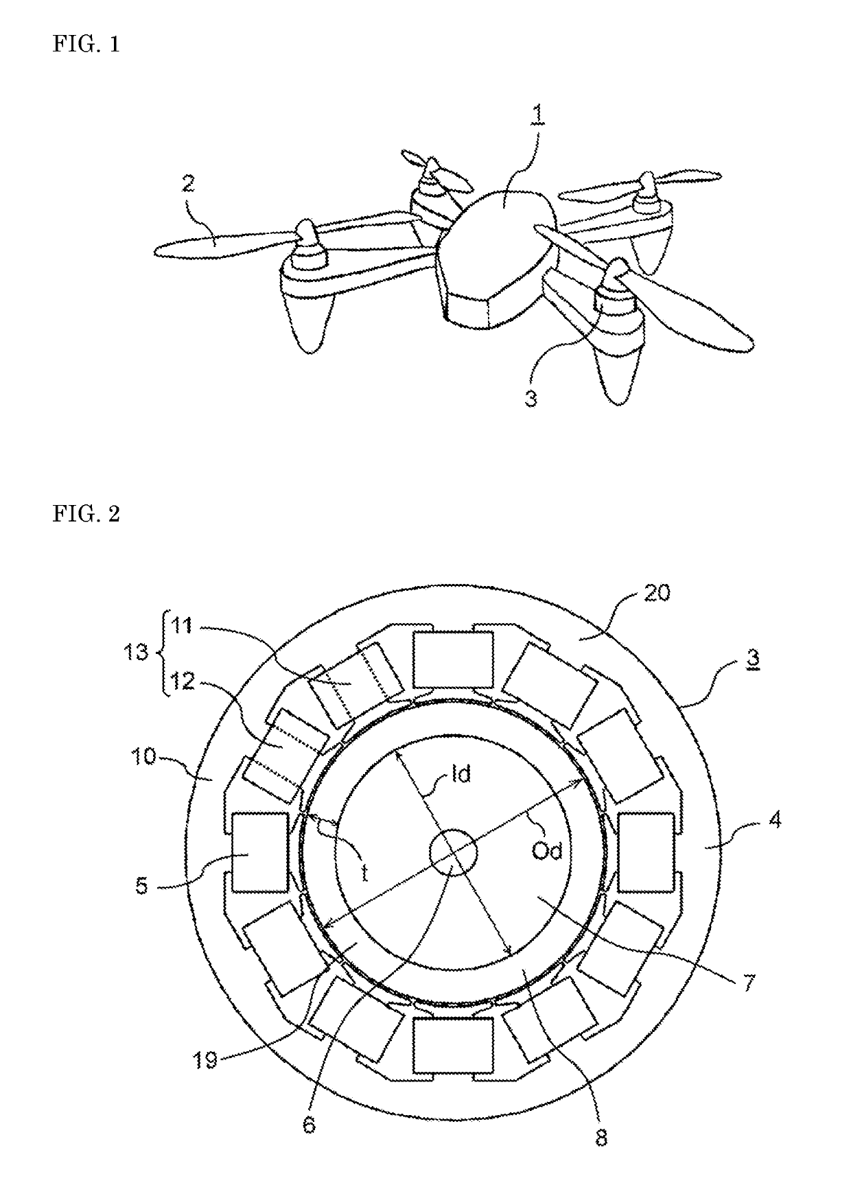
[0021]FIG. 1 is an external view of flying device 1 according to an exemplary embodiment of the present invention. Flying device 1 includes motor element 3 serving as a driving source for each of a plurality of rotary vanes 2, and a drive circuit that controls a stator current supplied to stator windings. Flying device 1 further includes a power supply, a control information communication unit, and a load carrying unit. For example, the power supply supplies power to the drive circuit. A secondary battery or a primary battery is used as the power supply.

[0022]FIG. 2 depicts motor element 3 ...


PUM


Abstract

A flying device includes a plurality of rotary vanes, a motor element serving as a driving source for each of the plurality of rotary vanes, the motor element driving and rotating a main shaft of the rotary vanes, and a drive circuit. The motor element includes a stator, a rotor, and a pair of bearings. The stator includes a stator core having an annular yoke and a plurality of teeth projecting inward from the annular yoke, and stator windings wound respectively around the plurality of teeth of the stator core. The rotor includes a permanent magnet of a cylindrical shape located inside the stator core via a gap, the permanent magnet being positioned counter to the plurality of teeth, a rotor yoke in contact with a cylindrical inner wall surface of the permanent magnet, and a shaft pivotally supported at an axis of the rotor yoke, the shaft being connected to the main shaft. The pair of bearings pivotally support the shaft to allow the shaft to rotate freely, and are located respectively on both sides of a direction of a rotating shaft of the rotor. The permanent magnet has anisotropically arranged magnetic poles, and a number of the magnetic poles is P representing an even number. The permanent magnet is configured such that the rotor yoke is smaller in weight than the permanent magnet. The drive circuit controls a stator current supplied to the stator windings.

Description

TECHNICAL FIELD[0001]The present invention relates to a flying device having a motor element serving as a driving source for rotary vanes.BACKGROUND ART[0002]Remote-controlled small flying devices that are used as toys or industrial devices are known. A large number of specific examples of such flying devices have been around for years since 1980s. Between such a small flying device and a remote control device that remote-controls the flying device, control information is transmitted through wired communication or wireless communication using radio waves or light. An internal-combustion engine light in weight is used as a driving source for rotary vanes of the small flying device. The small flying device has small lift, and is therefore not intended for carrying a person or transporting a heavy object, such as a freight, by air but is used as a remoted-controlled, small unmanned aircraft.[0003]In recent years, miniaturization and performance improvement of secondary batteries have l...

Claims


Application Information

Patent Timeline
IPC IPC(8): B64C27/08B64C39/02B64D27/24H02K1/27
CPCB64C27/08B64C39/02B64D27/24H02K1/27B64C2201/042B64C2201/027B64C2201/108H02K1/278H02K1/02H01F1/0577B64C39/024B64U50/19H02K1/22Y02T50/40Y02T50/60B64U10/13B64U30/20
Inventor TSUTSUMI, SHINICHIYOSHIKAWA, YUICHIKOYAMA, SHONUKADA, KEIICHIROUEDANAKADE, YUKI
Owner PANASONIC INTELLECTUAL PROPERTY MANAGEMENT CO LTD
Why Eureka
Try Eureka