Time-of-flight mass spectrometer

a mass spectrometer and time-of-flight technology, applied in the field of time-of-flight mass spectrometers, can solve the problems of limiting the energy convergence of the ion reflector, reducing the mass-resolving power, and it is practically impossible to arrange the ion ejector and the detector on the same straight line, so as to reduce the resolving power, increase the amount of ions reaching the detector, and accurately remove the

Active Publication Date: 2019-08-08
SHIMADZU CORP
View PDF1 Cites 1 Cited by
  • Summary
  • Abstract
  • Description
  • Claims
  • Application Information

AI Technical Summary

Benefits of technology

[0016]With the time-of-flight mass spectrometer according to the present invention, ions which may cause a decrease in the resolving power can be accurately removed in the middle of their flight in the free flight space. Therefore, it is possible to increase the amount of ions reaching the detector and thereby achieve a high level of analytical sensiti...

Problems solved by technology

However, there is a limit of the energy convergence by the ion reflector.
Therefore, if the variation in the initial energy is equal to or greater than a certain extent, a considerable deviation of the flight trajectory occurs, causing a decrease in the mass-resolving power.
However, it is practically impossible to arrange the ion ejector and the detector on the same straight line.
This results in a variation in the time of flight and causes a decrease in the resolving power.
However, the use of such a shielding plate for blocking ions to improve the resolving power blocks more ions than necessary, i.e. including ions which are practically unlikely to decrease the resolving power.
This causes the problem t...

Method used


Image

  • Time-of-flight mass spectrometer
  • Time-of-flight mass spectrometer

Examples


Embodiment Construction

[0020]A reflectron TOFMS as one embodiment of the present invention is hereinafter described with reference to the attached drawings.

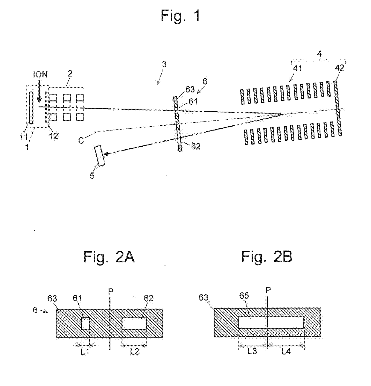
[0021]FIG. 1 is a schematic configuration diagram of the reflectron TOFMS in the present embodiment.

[0022]The reflectron TOFMS in the present embodiment is an orthogonal acceleration TOFMS. It includes: an orthogonal accelerator 1 including a plate-shaped push-out electrode 11 and a grid electrode 12; an ion-converging lens 2, which is an Einzel lens; a free flight space 3 with no electric field; an ion reflector 4 including a plurality of reflecting electrodes 41 and a back plate 42; and a detector 5 for detecting ions. Though not shown, the free flight space 3 and the ion reflector 4 are placed within a drift tube maintained in a high vacuum state.

[0023]An example of the reflecting electrode 41 is a plate-shaped electrode with a rectangular opening, as in the device described in Patent Literature 1. A plurality of reflecting electrodes 41 are arrayed...


PUM


Abstract

A shielding plate 6 having a forward-side slit opening 61 and return-side slit opening 62 is placed in a free flight space 3 with no electric field. Ions which significantly deviate from a reference path are removed by the shielding plate 6 on both the forward-side and return-side paths. The opening width of the forward-side slit opening 61 is smaller than that of the return-side slit opening 62. Those opening widths and the placement position of the shielding plate 6 are determined based on the result of an ion trajectory calculation by accurate simulation. As compared to a conventional device with a shielding plate placed only on the return side, the present configuration allows for an increase in the opening width of the return-side slit opening while achieving the same level of resolving power. The ion transmission ratio is thereby improved, and the analytical sensitivity is enhanced.

Description

TECHNICAL FIELD[0001]The present invention relates to a time-of-flight mass spectrometer, and more specifically, to a reflectron time-of-flight mass spectrometer using an ion reflector.BACKGROUND ART[0002]A time-of-flight mass spectrometer (which may be hereinafter abbreviated as the “TOFMS” according to a conventional usage) is a device in which various ions derived from a sample are made to fly a specific distance, and the time of flight is measured for each ion to calculate the mass-to-charge ratio m / z of the ion based on the fact that the flight speed of each ion depends on its mass-to-charge ratios when the ions are accelerated by the same amount of energy. In the TOFMS, the flight speed of an ion depends on the amount of initial energy imparted from an electric field or the like. Therefore, the mass-resolving power of the device is affected by the spread (variation) in the initial energy of an ion packet, i.e. a cluster of ions having the same mass-to-charge ratio.[0003]One me...

Claims


Application Information

Patent Timeline
IPC IPC(8): H01J49/40H01J49/00
CPCH01J49/403H01J49/0086H01J49/067H01J49/405
Inventor FUJITA, RYO
Owner SHIMADZU CORP
Why Eureka
Try Eureka