Optical detector for an optical detection

a technology of optical detection and optical detector, applied in the direction of optical radiation measurement, sustainable manufacturing/processing, instruments, etc., can solve the problem of quite challenging use of a multitude of filters

Active Publication Date: 2019-09-12
TRINAMIX GMBH
View PDF0 Cites 31 Cited by
  • Summary
  • Abstract
  • Description
  • Claims
  • Application Information

AI Technical Summary

Benefits of technology

[0076]Further, it may be feasible to provide an optical element which may be designed for alternatively supplying the incident light beam to the optical filter and to the second optical filter, thus allowing the incident light beam alternatively impinging the sensor layer through the optical filter and the second optical filter. In this particular embodiment, the modified light beam illuminating the sensor layer through the optical filter may be designated as a “measuring beam”, while the modified light beam illuminating the sensor layer through the second optical filter may be designed as a “reference beam”, or vice-versa. Particularly preferred, the evaluation device may, in this embodiment, further be designed for comparing the sensor signals as generated by the measuring beam and the reference beam for refined evaluation purposes. By way of example, it may be possible to arrange properties of the measuring beam and the reference beam in a manner that they can be canceled out directly within the sensor layer, t

Problems solved by technology

However, using a multitude of filters can be quite challenging with

Method used


Image

  • Optical detector for an optical detection
  • Optical detector for an optical detection
  • Optical detector for an optical detection

Examples


Embodiment Construction

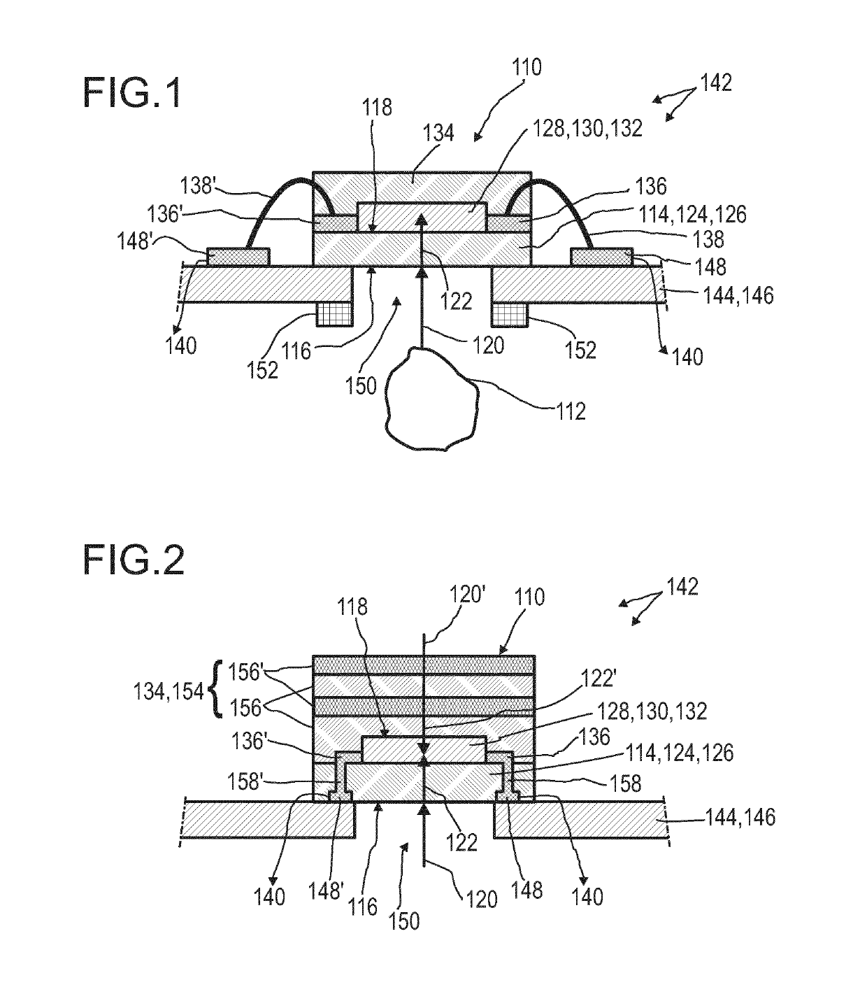
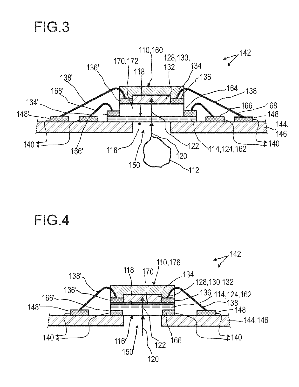
[0389]FIGS. 1 to 4 illustrate each, in a highly schematic fashion, an exemplary embodiment of an optical detector 110 according to the present invention. Herein, the detector 110 is adapted for optical detection, in particular, for detecting at least one wavelength in at least a partition of a spectral range, wherein the desired partition of the spectral range may be selected from the ultraviolet (UV), the visible (VIS) and / or the infrared (IR) spectral range, wherein the IR range, i.e. the spectral range of 760 nm to 1000 μm, and, especially, the mid infrared (MidIR) spectral range, i.e. the spectral range of 1.5 μm to 15 μm, may be preferred.

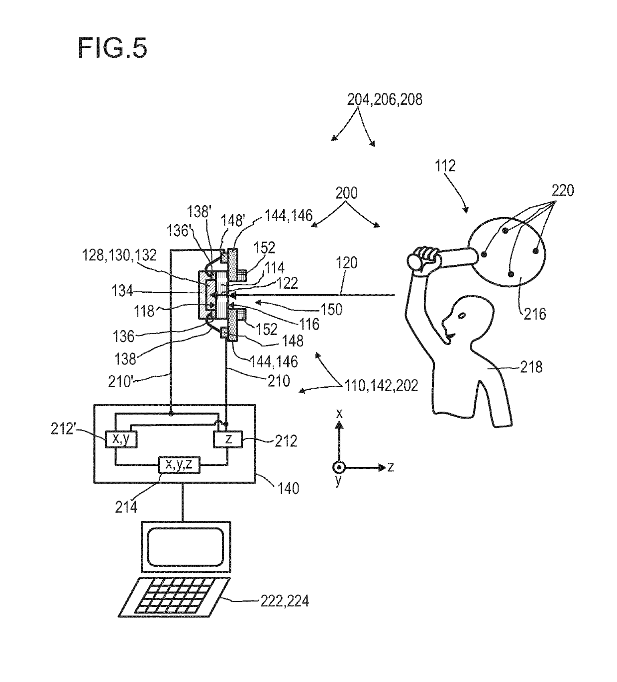
[0390]Specifically, the detector may be designed for sensing at least one optically conceivable property of at least one object 112. In particular, the optically conceivable property determinable by the detector 110 may be selected from at least one of an optical property and / or a geometric property of the object 112. By way of example, the op...


PUM


Abstract

The invention relates to an optical detector (110) for an optical detection, in particular, of radiation within the infrared spectral range, specifically, with regard to sensing at least one optically conceivable property of an object (112). More particular, the optical detector (110) may be used for determining transmissivity, absorption, emission, reflectance, and/or a position of at least one object (112). Further, the invention relates to a method for manufacturing the optical detector (110) and to various uses of the optical detector (110). The optical detector (110) comprises —an optical filter (114) having at least a first surface (116) and a second surface (118), the second surface (118) being located oppositely with respect to the first surface (116), wherein the optical filter (114) is designed for allowing an incident light beam (120) received by the first surface (116) to pass through the optical filter (114) to the second surface (118), thereby generating a modified light beam (122) by modifying a spectral composition of the incident light beam (120); —a sensor layer (128) comprising a photosensitive material (130) being deposited on the second surface (118) of the optical filter (114), wherein the sensor layer (128) is designed to generate at least one sensor signal in a manner dependent on an illumination of the sensor layer (128) by the modified light beam (122); and —an evaluation device (140) designed to generate at least one item of information provided by the incident light beam (120) by evaluating the sensor signal. The optical detector (110) constitutes an improved simple, cost-efficient and, still, reliable detector for detecting optical radiation, especially within the infrared spectral range, specifically with regard to sensing at least one of transmissivity, absorption, emission and reflectance. Hereby, the optical detector (110) is capable of effectively removing stray light as far as possible.

Description

FIELD OF THE INVENTION[0001]The invention relates to an optical detector for an optical detection, in particular, of radiation within the infrared spectral range, specifically, with regard to sensing at least one optically conceivable property of an object. More particular, the detector may be used for determining transmissivity, absorption, emission, reflectance, and / or a position of at least one object. Furthermore, the invention relates to a human-machine interface, an entertainment device, a scanning system, a tracking system, a stereoscopic system, and a camera. Further, the invention relates to a method for manufacturing the optical detector and to various uses of the optical detector. Such devices, methods and uses can be employed for example in various areas of daily life, gaming, traffic technology, mapping of spaces, production technology, security technology, medical technology or in the sciences. However, further applications are possible.PRIOR ART[0002]Optical detectors...

Claims


Application Information

Patent Timeline
IPC IPC(8): G01J5/20G01J5/08H01L31/0203H01L31/0216H01L31/09H01L31/0296H01L31/032
CPCH01L31/09H01L31/0203G01J5/0825G01J5/0831H01L31/0216H01L31/0326H01L31/0322G01J5/20H01L31/02966H01L31/0324H01L31/0296G01J5/04H01L21/02568H01G9/20H01L31/02161H01L31/02162H01L31/02165Y02E10/541Y02P70/50G01J5/0816G01J5/59
Inventor VALOUCH, SEBASTIANSEND, ROBERTBRUDER, INGMARHERMES, WILFRIED
Owner TRINAMIX GMBH
Why Eureka
Try Eureka