Balancing a multi-cell battery

Active Publication Date: 2019-09-12
CORVUS ENERGY INC
View PDF0 Cites 6 Cited by
  • Summary
  • Abstract
  • Description
  • Claims
  • Application Information

AI Technical Summary

Benefits of technology

[0029]The method may further comprise determining, for each unbalanced cell, whether a current drawn from the unbalanced cell is within a predetermined current range and, if so, carrying out the balancing of the unbalanced cell. Thus, stored energy may be conserved and heat generation may be minimised.
[0030]The method may further compri

Problems solved by technology

Since the cells are arranged in series, this will result in lower effective capacity, as charging must be stopped when the cell with the highest voltage reaches its upper voltage limit, and discharging must be stopped when the cell with the lowest voltage reaches its lower voltage limit.
One particular issue with the operation of such batteries is the requirement to take a battery module (or indeed an entire battery pack) offline in order to balance the cells.
However, measuring the voltage of a cell while the battery

Method used


Image

  • Balancing a multi-cell battery
  • Balancing a multi-cell battery
  • Balancing a multi-cell battery

Examples


Embodiment Construction

[0049]The present disclosure seeks to provide improved methods of balancing a multi-cell battery. While various embodiments of the disclosure are described below, the disclosure is not limited to these embodiments, and variations of these embodiments may well fall within the scope of the disclosure which is to be limited only by the appended claims.

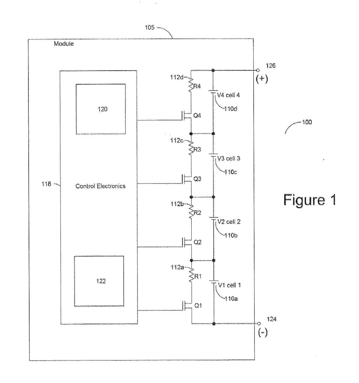
[0050]Turning to FIG. 1, there is shown a circuit diagram of a system 100 for balancing a multi-cell battery, in accordance with an embodiment of the disclosure. System 100 comprises a battery module 105 having a plurality of serially connected lithium-ion cells 110a-d. Note that although in the present embodiment cells 110a-d are represented as single cells, in other embodiments each of cells 110a-d may be a series element comprising one or more cells in parallel. In addition, although the embodiment of FIG. 1 shows four cells in series arrangement, the disclosure embraces battery modules with any number of cells.

[0051]Each cell 110a-d i...


PUM


Abstract

There is described a method of balancing a multi-cell battery. An alignment distance for each cell of the multi-cell battery is determined. The alignment distance defines a change in charge quantity required to achieve a target alignment point, based on a current charge quantity of the cell. Based on the determined alignment distances, one or more unbalanced cells are identified. Each unbalanced cell is then balanced by adjusting its current charge quantity according to the alignment distances. In one embodiment, the target alignment point is a target state of charge. In another embodiment, the target alignment point is a target charge quantity.

Description

FIELD OF THE DISCLOSURE[0001]The present disclosure relates to a method of balancing a multi-cell battery, such as a rechargeable lithium-ion battery as used in the maritime industry.Background to the Disclosure[0002]One type of rechargeable battery is a lithium-ion battery, comprising a number of serially connected cells. The battery is typically housed in an enclosure to form a battery module. During normal operating conditions, electrical energy is converted to and stored as chemical energy during charging, and stored chemical energy is converted to electrical energy during discharging.[0003]The cells within the module differ slightly in capacity and other parameters due to acceptable manufacturing tolerances. During use, and especially after repeated charging and discharging of the battery (i.e. after repeated charging-discharging cycles), the slight differences in the cells will gradually cause the cells to settle at voltages that differ from each other. Since the cells are arr...

Claims


Application Information

Patent Timeline
IPC IPC(8): H02J7/00H01M10/42H01M10/44H01M10/48
CPCH02J7/0014H01M2010/4271H01M10/425H01M10/441H01M10/482H01M10/48H02J7/0016H02J7/0048H02J7/14B60L58/22B60L58/13B60L58/16H02J7/005Y02E60/10Y02T10/70
Inventor TANG, SIU LUN ISAACLOKHORST, DAVID MAURICE
Owner CORVUS ENERGY INC
Why Eureka
Try Eureka