X-Ray Tube Casing With Integral Heat Exchanger

Active Publication Date: 2019-10-03
GE PRECISION HEALTHCARE LLC
View PDF4 Cites 0 Cited by
  • Summary
  • Abstract
  • Description
  • Claims
  • Application Information

AI Technical Summary

Benefits of technology

The patent is about an improved design for an x-ray tube casing. The casing is made of metal and has cooling channels embedded within it to increase heat exchange. It also has a close tolerance manufacturing process that ensures a snug fit with the x-ray tube insert, reducing the size of the oil gap and improving contact between the two for better heat transfer. A manifold is included to improve cooling efficiency. Overall, this design provides better cooling and performance for the x-ray tube.

Problems solved by technology

Further, the size of the tube casing 10′, including the heat exchanger 24′ / cooling circuit 25′ connected and / or mounted to the exterior of the casing 10′, significantly increases the overall size and weight of the casing 10′, limiting the degree of oblique imaging angles around the patient that can be utilized and compromising the quality of exam performed.

Method used


Image

  • X-Ray Tube Casing With Integral Heat Exchanger
  • X-Ray Tube Casing With Integral Heat Exchanger
  • X-Ray Tube Casing With Integral Heat Exchanger

Examples


Embodiment Construction

[0039]In the following detailed description, reference is made to the accompanying drawings that form a part hereof, and in which is shown by way of illustration specific embodiments, which may be practiced. These embodiments are described in sufficient detail to enable those skilled in the art to practice the embodiments, and it is to be understood that other embodiments may be utilized and that logical, mechanical, electrical and other changes may be made without departing from the scope of the embodiments. The following detailed description is, therefore, not to be taken in a limiting sense.

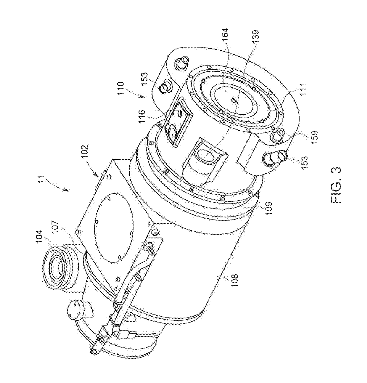
[0040]Looking now at FIGS. 3 and 4, in the illustrated exemplary embodiment the x-ray tube insert (not shown) is disposed within an x-ray tube casing 100 to form the x-ray tube 11. The casing 100 includes a hollow housing or body 102, a high voltage (HV) connector / end cap 104 secured to the housing 102 adjacent the cathode assembly (not shown) and a cover plate 106 (FIG. 10) secured to the hou...


PUM


Abstract

An x-ray tube casing is provided which includes a housing having a heat exchanger integrally formed thereon in an additive manufacturing process. The additive manufacturing process allows for tight tolerances with regard to the structure for the casing and the internal passages of the heat exchanger to significantly reduce the size and weight of the casing. The casing additionally includes a fluid distribution manifold that effectively distributes the cooling fluid within the casing to more efficiently provide cooling to the x-ray tube insert disposed within the casing.

Description

CROSS-REFERENCE TO RELATED APPLICATIONS[0001]This application claims priority as a continuation-in-part of co-owned and co-pending U.S. Non-Provisional Patent Application Ser. No. 15 / 630,409, entitled X-Ray Tube Casing, filed on Jun. 22, 2017, the entirety of which is expressly incorporated herein by reference for all purposes.FIELD AND BACKGROUND OF THE DISCLOSURE[0002]The invention relates generally to x-ray tubes, and more particularly to a casing for enclosing the various components of the x-ray tube.[0003]X-ray systems may include an x-ray tube, a detector, and a support structure for the x-ray tube and the detector. In operation, an imaging table, on which an object is positioned, may be located between the x-ray tube and the detector. The x-ray tube typically emits radiation, such as x-rays, toward the object. The radiation passes through the object on the imaging table and impinges on the detector, As radiation passes through the object, internal structures of the object cau...

Claims


Application Information

Patent Timeline
IPC IPC(8): H05G1/02H01J5/02H01J35/06H01J35/16H01J35/24H05G1/04F04D25/00F04D29/58
CPCH01J2235/12H05G1/04H01J35/16F04D25/00H01J35/24F04D29/58H01J5/02H01J35/065H05G1/025
Inventor ROGERS, CAREY S.NAIR, ANUP G.DESROSIERS, ANDREW J.RAJE, SIDSHIBIYA, CASSIDY C.
Owner GE PRECISION HEALTHCARE LLC
Why Eureka
Try Eureka