
Spectral narrowing module, refined spectral line device and method therefor

a narrowing module and narrowing technology, applied in semiconductor lasers, basic electric elements, laser details, etc., can solve the problems of low power, not very tunable and especially expensive, and light sources currently on the market occupy a significant linewidth, and achieve simple and inexpensive solutions, poor spectral quality, and small linewidth

Active Publication Date: 2019-10-10
UNIV DE RENNES I +1
View PDF0 Cites 1 Cited by
  • Summary
  • Abstract
  • Description
  • Claims
  • Application Information

AI Technical Summary

Benefits of technology

The present invention relates to a refined spectral line device that can use any light source and has a wide range of applications. The device uses a DFB laser that is cost-effective and energy-efficient. The refined spectral line device offers simultaneously a small linewidth, a great tunability, an extremely wide operating wavelength range, and a compatibility with hostile environments including the airborne and space environment. The device has a low weight, a moderate energy consumption, and a low cost. The invention also introduces a first modulated light beam into the first light source to narrow its spectral line. This allows the refined spectral line device to produce a signal light beam with the same properties as the incident light beam.

Problems solved by technology

Nevertheless, the light sources currently on the market comprise a significant linewidth.
Of course, there are light sources having a small linewidth, however they have the drawback of being often complex, with low power, not very tunable and especially expensive.

Method used


Image

  • Spectral narrowing module, refined spectral line device and method therefor
  • Spectral narrowing module, refined spectral line device and method therefor
  • Spectral narrowing module, refined spectral line device and method therefor

Examples


second embodiment

GENERAL DESCRIPTION OF A SECOND EMBODIMENT

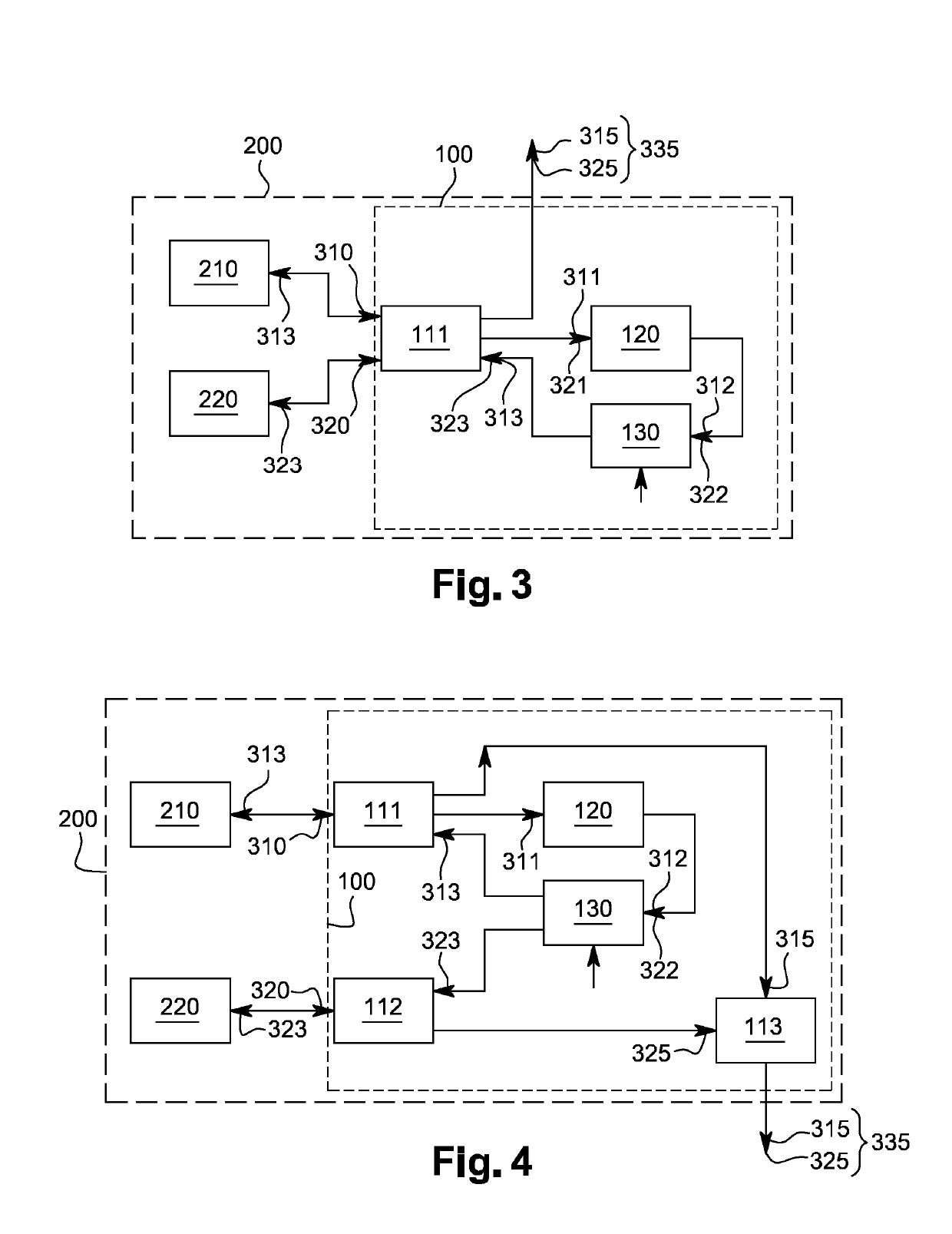
[0105]The second embodiment shown in FIG. 3 is roughly similar to the first embodiment. Indeed, in addition to the first light source 210, the second embodiment comprises a second light source 220. The second light source 220 is transmitted to the first said at least one first coupler 111 via a medium such as glass, a gas, a crystal for example. The benefit of this arrangement is to narrow the two light sources, that is to say the first light source 210 and the second light source 220 or to narrow only the second light source 220 using the first light source 210.

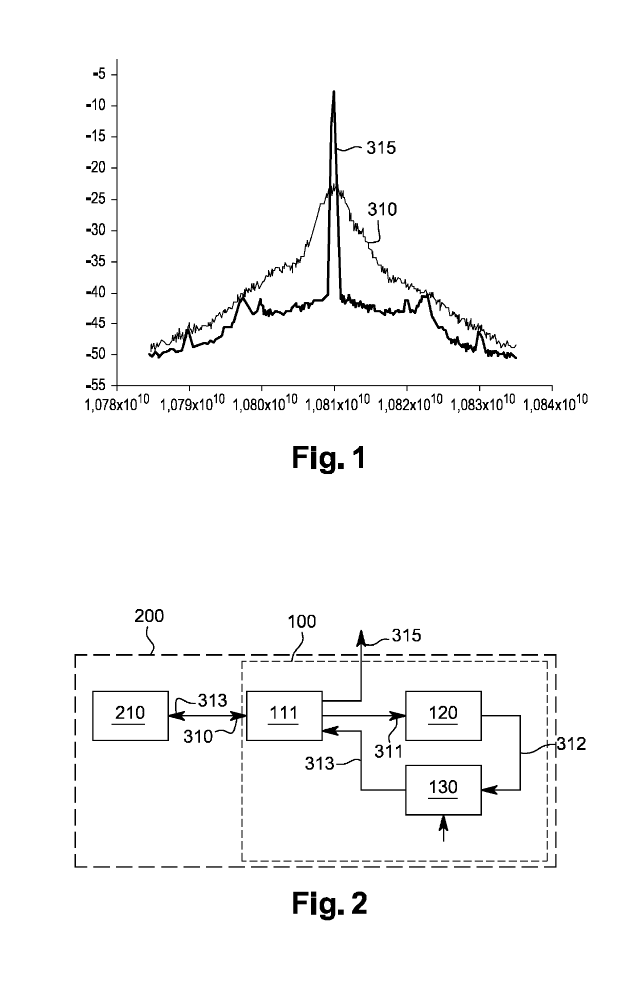
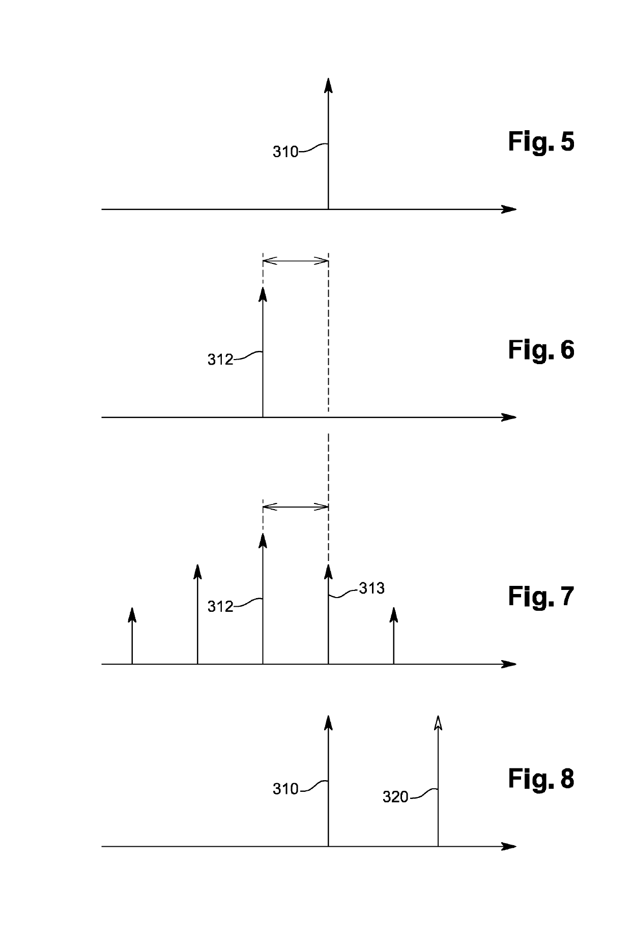
[0106]FIG. 8 shows the spectral line of the first light source 310 and the spectral line of the second light source 320. These two spectral lines are injected into the spectral narrowing module 100. As in the first embodiment, the spectral narrowing module 100 comprises a first said at least one first coupler 111, a Brillouin resonator 120 and a modulator 130.

[0107]As previously ment...

third embodiment

GENERAL DESCRIPTION OF A THIRD EMBODIMENT

[0113]In this third embodiment shown in FIG. 4, only the first light source 210 will be used to narrow the second light source 220. Indeed, in this configuration, the spectral narrowing module 100 comprises a first said at least one first coupler 111, a second said at least one first coupler 112, a third said at least one first coupler 113, a Brillouin resonator 120 and a modulator 130.

[0114]The first light source 210 emits a first light beam. The first said at least one first coupler 111 is configured to derive at least one first pumping light beam 311 from a first incident light beam 310 originating from said at least one first light source 210 and introduced into the spectral narrowing module 100. The first pumping light beam 311 is directed towards the Brillouin resonator 120.

[0115]This Brillouin resonator 120 is configured to generate, from at least one portion of said first pumping light beam 311, at least one first resonant light beam ...


PUM


Abstract

Many applications require the use of lasers with short optical ray lengths. However, at present, there is no module that makes it possible to refine a ray from a light source in a satisfactory manner, in particular one from a semiconductor laser. The invention relates to a spectral refinement method (500), a device with refined spectral line (200) comprising at least one light source (210) and a spectral refinement module (100). The latter includes at least one first coupler (111), a Brillouin resonator (120) and a modulator (130).

Description

CROSS REFERENCE TO RELATED APPLICATIONS[0001]This application is a National Stage of PCT Application No. PCT / FR2017 / 051491 filed on Jun. 12, 2017, which claims priority to French Patent Application No. 16 / 55456 filed on Jun. 13, 2016 the contents each of which are incorporated herein by reference thereto.FIELD OF THE INVENTION[0002]The field of the present invention concerns the one of the light sources producing an amplified light beam by stimulated emission of radiation. It particularly, but not exclusively, concerns the field of the spectral narrowing modules. More specifically, the present invention concerns the methods for spectrally refining a light source by introducing a previously spectrally refined light beam.PRIOR ART[0003]Nowadays, many applications require the use of a light source having small optical linewidths. These applications are generally optical metrology, spectroscopy, telecommunications, radar systems, atom manipulation and atomic clocks. Nevertheless, the li...

Claims


Application Information

Patent Timeline
Patent Type & Authority Applications(United States)
IPC IPC(8): H01S3/30H01S3/00H01S3/106
CPCH01S2302/02H01S3/106H01S3/302H01S3/0085H01S3/10092H01S5/0656
Inventor ALOUINI, MEHDIDANION, GWENNAËLVALLET, MARC
Owner UNIV DE RENNES I
Learn More