On-Board Controller
- Summary
- Abstract
- Description
- Claims
- Application Information
AI Technical Summary
Benefits of technology
Problems solved by technology
Method used
Image


Examples
embodiments
First Embodiment
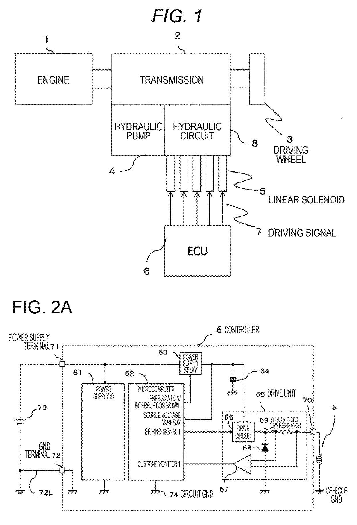
[0031]FIG. 1 is a schematic configuration diagram of a vehicular transmission system to which the present invention is applied.
[0032]In FIG. 1, an engine 1 drives a driving wheel 3 via a transmission 2. Operation of the transmission 2 is controlled by a hydraulic circuit 8 to which hydraulic pressure is supplied from a hydraulic pump 4.
[0033]In addition, the driving of the hydraulic circuit 8 is controlled by a plurality of linear solenoids 5.
[0034]The driving of the linear solenoids 5 is controlled by a driving signal 7 supplied from an electronic contorol unit (ECU) (controller) 6.
[0035]FIG. 2 is an internal configuration diagram of the ECU (controller) 6 shown in FIG. 1.
[0036]In FIG. 2, the controller 6 includes a power supply IC 61, a microcomputer 62, a power supply relay 63, a smoothing electrolytic capacitor 64, a drive circuit (switch element) 66, a differential amplifier 67, a regenerative current diode 68, a shunt resistor 69, a power supply terminal 71, a ...
second embodiment
[0069]Next, a second embodiment of the present invention will be described.
[0070]In the first embodiment, as shown in FIG. 3, a current flowing through the shunt resistor 69 is monitored, and based on the monitored current value, there is calculated a voltage range (voltage threshold) at the positive electrode of the smoothing electrolytic capacitor 64 in the case of disconnection of the ground wire 72L.
[0071]Meanwhile, in the second embodiment, a voltage at the positive electrode of a smoothing electrolytic capacitor 64 is monitored. Based on the monitored voltage value, there is calculated a current range (current threshold) of a current flowing through a shunt resistor 69 in the case of disconnection of a ground wire 72L. Thus, it is determined whether the ground wire 72L has been disconnected, by comparing the calculated current threshold with a monitored current flowing through the shunt resistor 69.
[0072]A schematic configuration diagram of a controller according to the second...
third embodiment
[0081]Next, a third embodiment of the present invention will be described.
[0082]In the third embodiment, it is determined that a ground wire 72L has been disconnected, based on a correlation between a voltage at the positive electrode of a smoothing electrolytic capacitor 64 and a current flowing through a shunt resistor 69 (a current flowing through a linear solenoid 5), as with the first and second embodiments.
[0083]In the case where an ON / OFF signal as a driving signal is supplied to a drive circuit 66 of a drive unit 65 while the ground wire 72L is disconnected, there arises a difference between a waveform of the voltage at the positive electrode of the smoothing electrolytic capacitor 64 and a waveform of the current flowing through the shunt resistor 69. The third embodiment focuses on the fact in determination of disconnection of the ground wire 72L.
[0084]FIG. 6 is a functional block diagram relating to detection of disconnection a microcomputer 62, shown in FIG. 2, according...
PUM
 Abstract
Description
Claims
Application Information