Intake control method and intake control device for internal combustion engine

a technology of internal combustion engine and intake control device, which is applied in the direction of electric control, machines/engines, mechanical equipment, etc., can solve the problems of backflow of egr gas, difficult to accurately control etc., to achieve accurate control of the intake air amount and the egr ratio, and reduce the opening degree , the effect of enabling egr control

Active Publication Date: 2019-10-31
NISSAN MOTOR CO LTD +1
View PDF0 Cites 2 Cited by
  • Summary
  • Abstract
  • Description
  • Claims
  • Application Information

AI Technical Summary

Benefits of technology

[0003]The control in the above document is intended for a so-called high-pressure EGR system (hereinafter, also called HP-EGR system) in which the EGR gas is introduced into a portion downstream of the intake throttle valve in the intake flow. In the portion downstream of the intake throttle valve in the intake flow, a negative pressure develops when the opening degree of the intake throttle valve decreases. Accordingly, in the HP-EGR system, a differential pressure between the exhaust side and the intake side necessary for recirculating the EGR gas is secured by the negative pressure that develops with the decrease in opening degree of the intake throttle valve.
[0004]On the other hand, for enabling EGR control in a wider operating region, a so-called low-pressure EGR system (hereinafter, also called LP-EGR system) has recently been proposed in which the EGR gas is introduced into a portion upstream of the intake throttle valve in the intake flow. The portion upstream of the intake throttle valve in the intake flow is of an approximately atmospheric pressure, so the differential pressure between the intake side and the exhaust side is small in the LP-EGR system as compared to that in the HP-EGR system. Thus, for example in a low-load operating region where the pressure on the exhaust side decreases, the pressure on the exhaust side may become lower than in the intake side due to exhaust pulsation, possibly causing backflow of the EGR gas. This arises a need, in the LP-EGR system, to provide an additional throttle valve (hereinafter, also called negative pressure generating valve) at a position upstream of the intake throttle valve in the intake flow, so as to secure the differential pressure between the intake side and the exhaust side necessary for introducing the EGR gas.
[0005]Incidentally, changing the opening degree of the negative pressure generating valve causes a change of a pressure (hereinafter, also called intake pressure) inside the intake passage from the negative pressure generating valve to the intake throttle valve. That is to say, even if the opening degree of the intake throttle valve and the opening degree of an EGR valve for adjusting the EGR ratio are unchanged, the intake air amount and the EGR ratio vary depending on the opening degree of the negative pressure generating valve. It is therefore difficult to accurately control the intake air amount and the EGR ratio by simply applying the control in the above document, as it is, to the LP-EGR system.
[0006]In view of the foregoing, an object of the present invention is to control the intake air amount and the EGR ratio with accuracy in an EGR system equipped with a negative pressure generating valve.
[0007]According to one embodiment of the present invention, an intake control method for an internal combustion engine comprising an intake throttle valve disposed in an intake passage and having a target opening degree set in accordance with a target fresh air amount determined for each operating point of the internal combustion engine, an EGR passage provided for communication between a portion in the intake passage upstream, in an intake flow, of the intake throttle valve and an exhaust passage, an EGR valve disposed in the EGR passage and having a target opening degree set in accordance with a target EGR gas amount determined for each said operating point, and a negative pressure generating valve disposed at a position in the intake passage upstream, in the intake flow, of a confluence with the EGR passage is provided. The control method comprising setting a target intake pressure, which is a target value of an intake pressure in the intake passage between the negative pressure generating valve and the intake throttle valve, necessary for performing EGR control in a state of an exhaust pressure determined for each said operating point. The control method also comprising setting a target total opening area, which is a sum of a target opening area of the EGR valve and a target opening area of the negative pressure generating valve, on the basis of the target intake pressure, the target fresh air amount, and the target EGR gas amount, and setting a target EGR valve opening area, which is an opening area of the EGR valve for achieving the target EGR gas amount, assuming that the negative pressure generating valve is fully open. Further, the control method comprising setting a value obtained by subtracting the target EGR valve opening area from the target total opening area to be a target negative pressure generating valve opening area, which is a target value of an opening area of the negative pressure generating valve.

Problems solved by technology

Thus, for example in a low-load operating region where the pressure on the exhaust side decreases, the pressure on the exhaust side may become lower than in the intake side due to exhaust pulsation, possibly causing backflow of the EGR gas.
It is therefore difficult to accurately control the intake air amount and the EGR ratio by simply applying the control in the above document, as it is, to the LP-EGR system.

Method used


Image

  • Intake control method and intake control device for internal combustion engine
  • Intake control method and intake control device for internal combustion engine
  • Intake control method and intake control device for internal combustion engine

Examples


Embodiment Construction

[0016]An embodiment of the present invention will be described below with reference to the accompanying drawings.

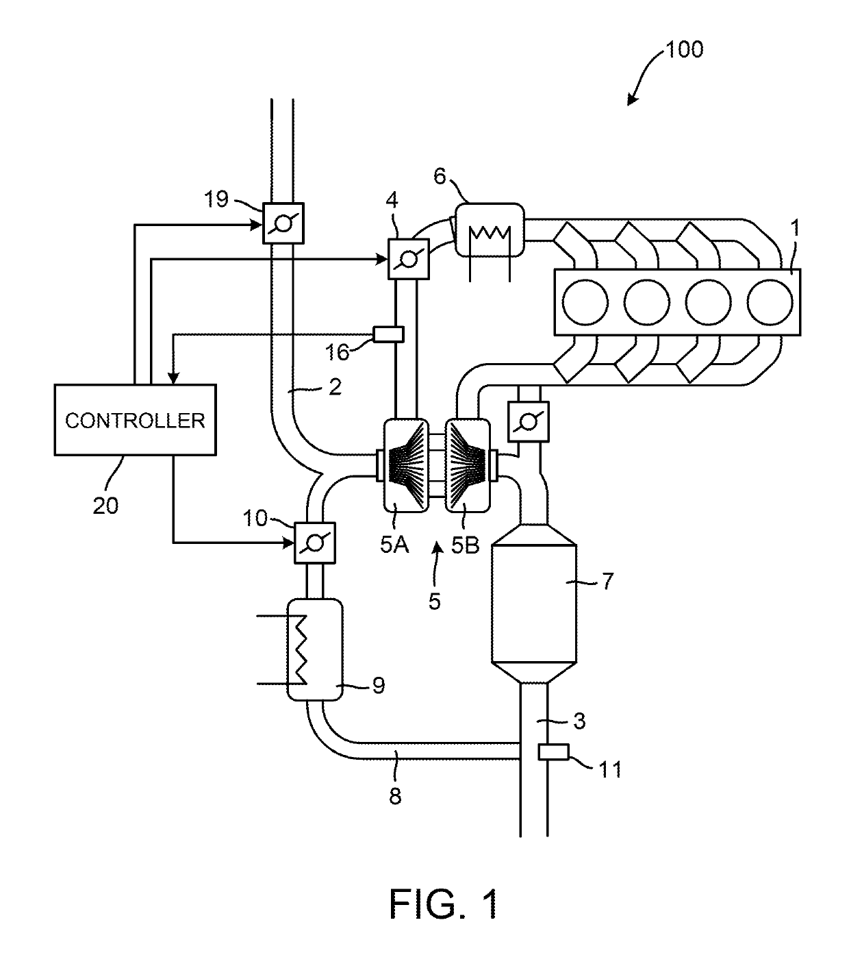
[0017]FIG. 1 is a schematic configuration diagram of an internal combustion engine system 100 according to a first embodiment.

[0018]An intake passage 2 has arranged thereon, from upstream in an intake flow, an air flow meter (not shown), a negative pressure generating valve (hereinafter, also called ADM / V) 19, a compressor 5A of a turbo supercharger 5, a throttle valve (hereinafter, also called TH / V) 4, and an intercooler 6.

[0019]While an intake air amount is detected using the air flow meter in the present embodiment, not limited thereto, the intake air amount may be detected or estimated in an arbitrary manner. For example, it may be estimated on the basis of, for example, the pressure in the intake passage 2 downstream of the TH / V 4 and the opening degree of the TH / V 4.

[0020]An exhaust passage 3 has arranged thereon, from upstream in an exhaust flow, a turbine 5B of th...


PUM


Abstract

An intake control method for an internal combustion engine equipped with a low-pressure EGR system includes setting a target intake pressure, which is a target value of an intake pressure in an intake passage between a negative pressure generating valve and an intake throttle valve, necessary for performing EGR control in a state of an exhaust pressure determined for each operating point, setting a target total opening area, which is a sum of a target opening area of an EGR valve and a target opening area of the negative pressure generating valve, on the basis of the target intake pressure, a target fresh air amount, and a target EGR gas amount, setting a target EGR valve opening area, which is an opening area of the EGR valve for achieving the target EGR gas amount, assuming that the negative pressure generating valve is fully open, and setting a value obtained by subtracting the target EGR valve opening area from the target total opening area to be a target negative pressure generating valve opening area, which is a target value of an opening area of the negative pressure generating valve.

Description

TECHNICAL FIELD[0001]The present invention relates to intake control for an internal combustion engine.BACKGROUND ART[0002]An internal combustion engine equipped with an exhaust gas recirculation device (hereinafter, also called EGR device) that recirculates a portion of the exhaust gas back into the intake line for improving fuel economy performance and environmental performance is known. Japanese Patent No. 3511849 discloses intake control for an internal combustion engine equipped with an EGR device. In this document, firstly, a total fresh air amount is calculated which is a sum of an intake air amount and a fresh-air equivalent amount that is obtained by converting the amount of recirculated exhaust gas (hereinafter, also called EGR gas) to the amount of air (hereinafter, also called fresh air) in the atmosphere. Next, a total opening area of an intake throttle valve and an EGR valve is calculated on the basis of the total fresh air amount. The total opening area is allocated a...

Claims


Application Information

Patent Timeline
Patent Type & Authority Applications(United States)
IPC IPC(8): F02D41/00F02M26/02
CPCF02M2026/001F02M26/02F02D41/0002F02D41/0047F02D2250/41F02M26/06F02D41/0065F02D2041/0017F02D41/0007F02D2200/0406F02M26/10Y02T10/12Y02T10/40F02D41/02F02M26/00
Inventor YONEKURA, KENGOTSUCHIDA, HIROFUMIHAMAMOTO, TAKAYUKI
Owner NISSAN MOTOR CO LTD
Why Eureka
Try Eureka