Fail-Safe Speed Monitoring of a Drive

Active Publication Date: 2019-11-07
SIEMENS ENERGY GLOBAL GMBH & CO KG
View PDF1 Cites 0 Cited by
  • Summary
  • Abstract
  • Description
  • Claims
  • Application Information

AI Technical Summary

Benefits of technology

[0005]In view of the foregoing, it is an object of the invention to provide a method for fail-safe monito

Problems solved by technology

For a method without the calculated substitute rotational speed, the feedback of target value and actual value (actual value captured by sensor) via closed-loop control do

Method used


Image

  • Fail-Safe Speed Monitoring of a Drive
  • Fail-Safe Speed Monitoring of a Drive

Examples


Embodiment Construction

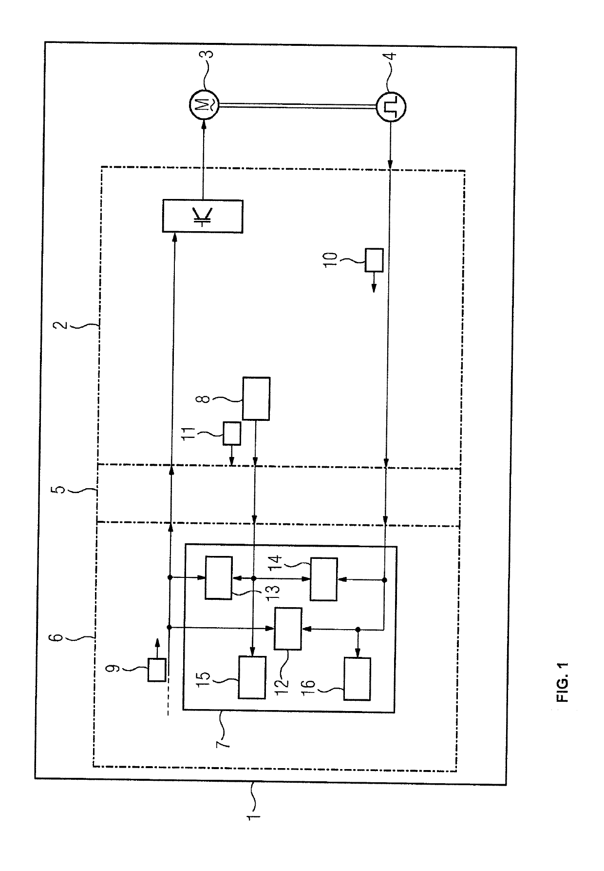
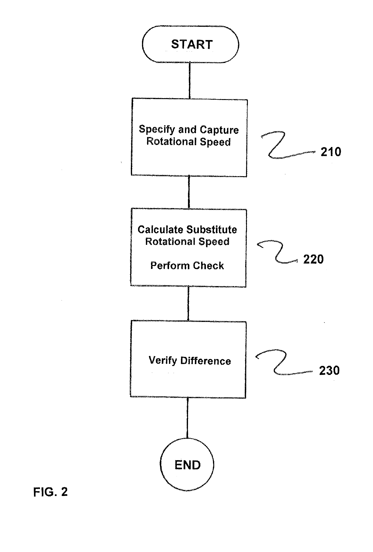
[0021]FIG. 1 shows a system 1 comprising a drive, which has a converter 2, a motor 3 and a rotational speed sensor 4, and a safety CPU 6 with a safety program 7. Converter 2 and safety CPU 6 are coupled together, e.g., via a field bus 5 as a communication connection. In the exemplary embodiment illustrated, the converter 2 itself has means 8 for calculating a substitute rotational speed 11. The substitute rotational speed 11 here is calculated from the initial frequency of the converter 2 in the case of three-phase drives or the quotient of EMF (electromotive force or terminal voltage) and magnetic flux in the case of direct-current drives. A target rotational speed 9 is specified to the converter 2, and the rotational speed sensor 4 returns an actual rotational speed 10.

[0022]Two of these three rotational speed values are now each verified in the safety program 7 of the safety CPU 6 for plausibility, i.e., a plausibility verification 12 occurs between the target rotational speed 9 ...


PUM


Abstract

A method for fail-safe monitoring of the speed of a drive that includes at least a converter, a motor, and a rotational speed sensor, wherein a target rotational speed is specified to the drive and an actual rotational speed is sensed via the sensor, where a substitute rotational speed is calculated and three plausibility checks are performed in a safety program of a safety CPU, the substitute rotational speed being determinable, for example, from the initial frequency of a converter or from the quotient of EMF and magnetic flux, in each case two of the following three values being checked: target rotational speed, actual rotational speed and substitute rotational speed to achieve a high safety integrity level while avoiding disadvantages of conventional solutions, and because the calculated substitute rotational speed is independent of the sensor, even sensor errors that are difficult or impossible to detect via conventional solutions become detectable.

Description

CROSS-REFERENCE TO RELATED APPLICATIONS[0001]This is a U.S. national stage of application No. PCT / EP2016 / 077273 filed Nov. 10, 2016. Priority is claimed on EP Application No. 15200824 filed Dec. 17, 2015, the content of which is incorporated herein by reference in its entirety.BACKGROUND OF THE INVENTION1. Field of the Invention[0002]The invention relates to a method for fail-safe monitoring of the speed of a drive, which has at least a converter, a motor and a rotational speed sensor, wherein a target rotational speed is specified to the drive and an actual rotational speed is captured by means of the rotational speed sensor, and also relates to a system comprising at least one drive, which has at least the converter, the motor and the rotational speed sensor, and means for performing the cited method, where the cited method is used to indirectly monitor the web speed of a material web which is moved by rollers in a paper machine, reel slitter or coater.2. Description of the Relate...

Claims


Application Information

Patent Timeline
IPC IPC(8): G01D5/244H02H7/08H02H7/093B65H18/18
CPCG01D5/24461G01D5/24466H02H7/0844B65H18/18H02H7/093B65H26/00G01P3/48G01P21/02H02P29/10B65H23/192B65H2513/11B65H2801/84B65H2513/10B65H2220/01B65H2220/02
Inventor CZERNY, WERNERMEINARDUS, MARTINRASENACK, WOLF-MARTINVLAIC, IULIU
Owner SIEMENS ENERGY GLOBAL GMBH & CO KG
Why Eureka
Try Eureka