Ultrasonic device, ultrasonic module, and ultrasonic measuring apparatus

a technology of ultrasonic module and ultrasonic measuring device, which is applied in the field of ultrasonic module and ultrasonic measuring apparatus, can solve the problems of reduced transmission and reception efficiency of ultrasonic wave, increased stiffness of the first vibration portion, and difficulty in achieving thin or compact piezoelectric body, etc., to achieve high improve transmission and reception efficiency, and high accuracy

Active Publication Date: 2019-11-14
SEIKO EPSON CORP
View PDF0 Cites 5 Cited by
  • Summary
  • Abstract
  • Description
  • Claims
  • Application Information

AI Technical Summary

Benefits of technology

[0011]In such a configuration, since the transmission transducer and the reception transducer are separately provided, it is possible to have characteristics suitable for transmitting the ultrasonic wave in the transmission transducer and to have characteristics suitable for receiving the ultrasonic wave in the reception transducer. Accordingly, it is possible to more improve transmission and reception efficiency of the ultrasonic wave, compared to a case where the transmission and the reception of the ultrasonic wave are performed in one ultrasonic transducer. In other words, it is possible to transmit an ultrasonic wave having a high acoustic pressure in the transmission of the ultrasonic wave, and it is possible to receive the ultrasonic wave with high receiving sensitivity and high accuracy in the reception of the ultrasonic wave.
[0034]In the application example, as described above, it is possible to improve the transmission and reception efficiency in the ultrasonic device. Hence, the controller controls the ultrasonic device, and thereby, through the transmission / reception process of the ultrasonic wave, which has high transmission and reception efficiency, it is possible to realize the ultrasonic measurement with high accuracy. For example, in a case of acquiring an internal tomographic image of the target subject based on measurement results of the ultrasonic measurement, it is possible to acquire the internal tomographic image with high accuracy.

Problems solved by technology

However, the bulk-type piezoelectric body needs to have a large thickness dimension, and thus it is difficult to achieve a thin or compact piezoelectric body.
Hence, when the ultrasonic transducer disclosed in JP-2002-271897 is an ultrasonic transducer for both of transmission and reception or ultrasonic transducers having the same configuration for both of transmission and reception is used, a problem arises in that transmission and reception efficiency of the ultrasonic wave is reduced.
Furthermore, when the thickness dimension of the transmitting piezoelectric film increases, the stiffness of the first vibration portion increases, and thus the first vibration portion is not easily bent.
In a case where a difference between the natural frequencies of the transmission transducer and the reception transducer is smaller than 0.2 MHz, as described above, the reception transducer resonates when the ultrasonic wave is transmitted, and thereby a large amount of noise is contained in the output voltage.

Method used


Image

  • Ultrasonic device, ultrasonic module, and ultrasonic measuring apparatus
  • Ultrasonic device, ultrasonic module, and ultrasonic measuring apparatus
  • Ultrasonic device, ultrasonic module, and ultrasonic measuring apparatus

Examples


embodiment

Operational Effects of Embodiment

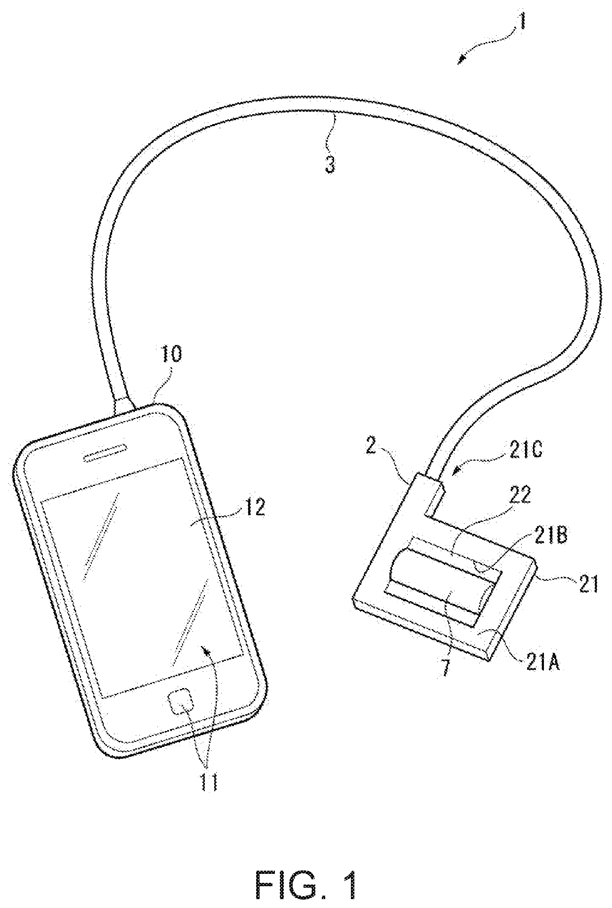
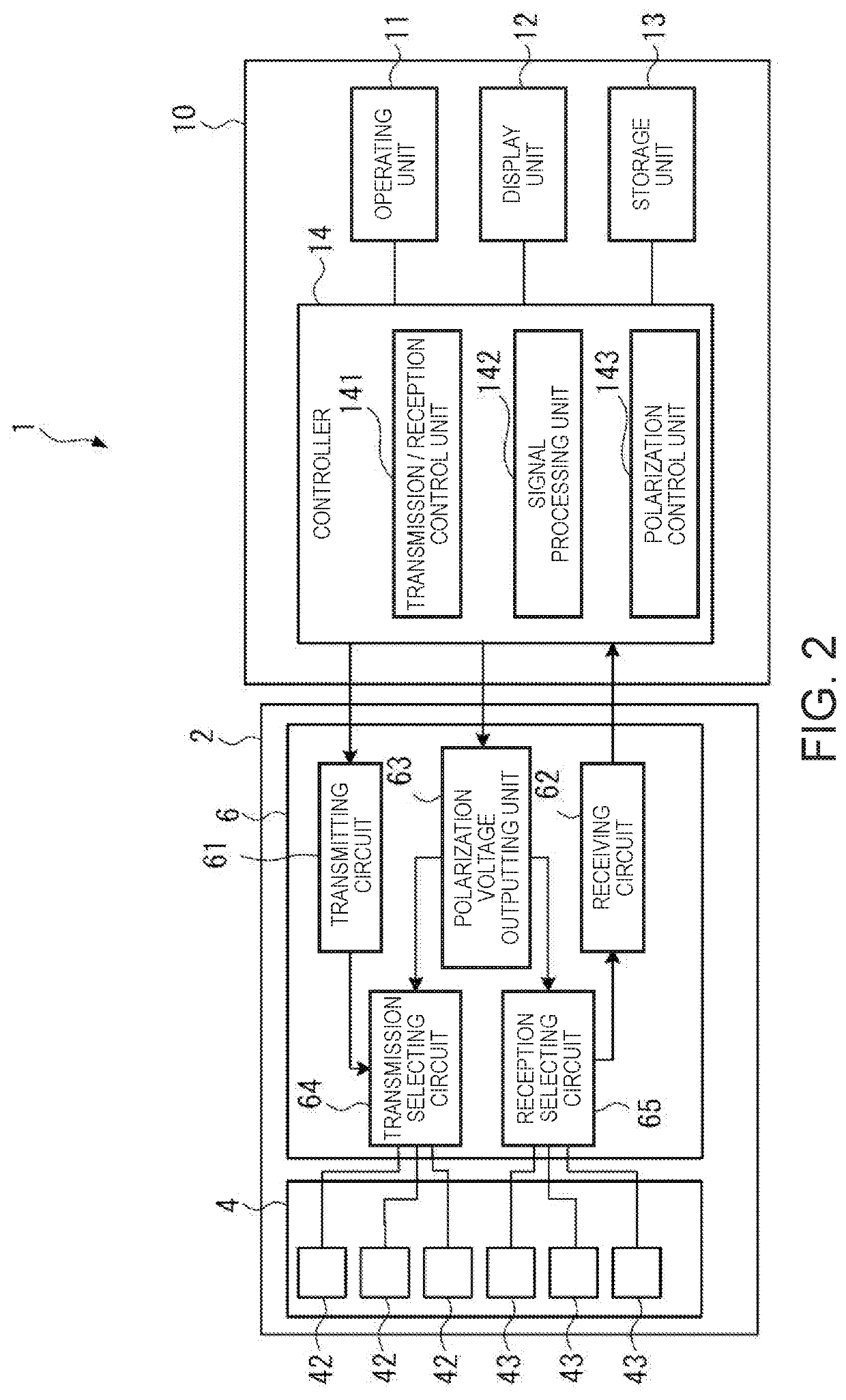
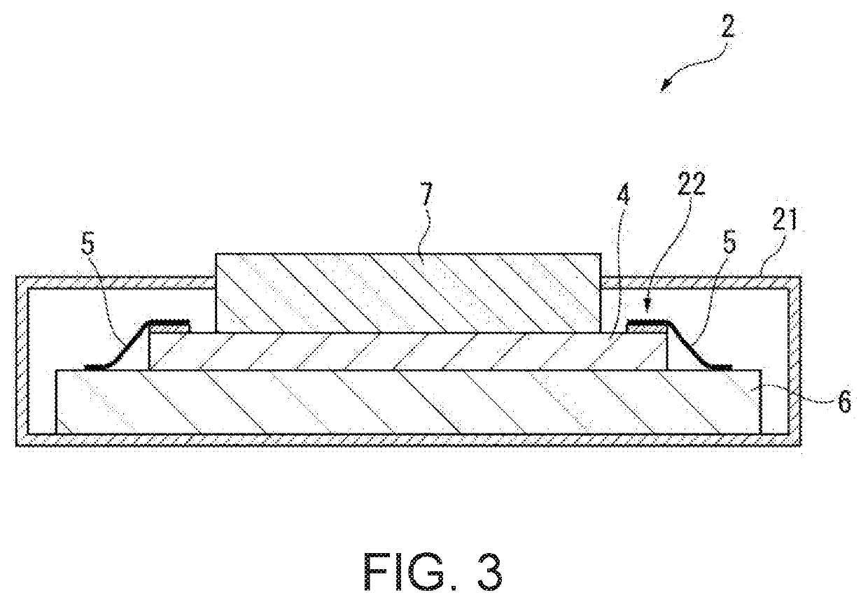
[0145]The ultrasonic device 4 of the embodiment includes the transmission transducer 421 and the reception transducer 431. The transmission transducer 421 is configured to have the support film 412 (first vibration portion 412A) that covers the first opening 411A of the element substrate 411 and the transmission piezoelectric element 413 provided on the first vibration portion 412A. The transmission piezoelectric element 413 includes the transmitting piezoelectric film 413B interposed between the lower electrode 413A and the upper electrode 415 in the thickness direction. In addition, the reception transducer 431 is configured to have the support film 412 (second vibration portion 412B) that covers the second opening 411B of the element substrate 411 and the reception piezoelectric element 414 provided on the second vibration portion 412B. The reception piezoelectric element 414 includes the receiving piezoelectric film 414B interposed between the lo...

modification examples

[0155]The invention is not limited to the embodiments described above, and the invention also includes a configuration obtained through modification, improvement, and an appropriate combination of the embodiments in a range in which it is possible to achieve the object of the invention.

[0156]In the embodiment described above, the difference between the thickness dimensions of the transmitting piezoelectric film 413B and the receiving piezoelectric film 414B is 350 nm or larger; however, the difference is not limited thereto. For example, as shown in FIG. 14, the thickness dimension to of the transmitting piezoelectric film 413B may be 650 nm, and the thickness dimension tB of the receiving piezoelectric film 414B may be 800 nm.

[0157]In the embodiment, the opening width LA of the first opening 411A is smaller than the opening width LB of the second opening 411B; however, the opening width is not limited thereto.

[0158]As described above, the natural frequency of the transmission trans...


PUM


Abstract

An ultrasonic device includes: a substrate provided with a first opening and a second opening; a support film that is provided on the substrate and blocks the first opening and the second opening; a transmitting piezoelectric film that is provided on the support film at a position which overlaps the first opening when viewed in a thickness direction of the substrate and is interposed between a pair of electrodes in the thickness direction of the substrate; and a receiving piezoelectric film that is provided on the support film at a position which overlaps the second opening when viewed in the thickness direction of the substrate and is interposed between a pair of electrodes in the thickness direction of the substrate. In the thickness direction of the substrate, a thickness dimension of the transmitting piezoelectric film is smaller than a thickness dimension of the receiving piezoelectric film.

Description

CROSS-REFERENCE TO RELATED APPLICATIONS[0001]This application is a U.S. National Stage Application of International Application No. PCT / JP2017 / 015635, filed on Apr. 18, 2017, and published in Japanese as WO 2017 / 188072 A1 on Nov. 2, 2017, which claims priority to Japanese Patent Application No. 2016-090953, filed on Apr. 28, 2016. The entire disclosures of the above applications are incorporated herein by reference.BACKGROUNDTechnical Field[0002]The present invention relates to an ultrasonic device, an ultrasonic module, and an ultrasonic measuring apparatus.Related Art[0003]In the related art, an ultrasonic transducer using a so-called bulk-type piezoelectric body has been known as an ultrasonic transducer that performs a transmitting process and a receiving process of an ultrasonic wave, the ultrasonic transducer including a piezoelectric body interposed between a pair of electrodes, transmitting the ultrasonic wave by applying a voltage between the electrodes and causing the piez...

Claims


Application Information

Patent Timeline
Patent Type & Authority Applications(United States)
IPC IPC(8): A61B8/00H04R17/00B06B1/02B06B1/06H01L41/04H01L41/053H01L41/08A61B8/13
CPCB06B1/0622A61B8/13B06B2201/76B06B1/0215A61B8/54H01L41/053H01L41/0825H04R17/00H01L41/042A61B8/14B06B1/0625A61B8/4427H10N39/00H10N30/1071H10N30/2047H10N30/88H10N30/802
Inventor MIYAZAWA, HIROMUITO, HIROSHINAKAMURA, TOMOAKIYAMADA, MASAYOSHIKIYOSE, KANECHIKAFUNASAKA, TSUKASA
Owner SEIKO EPSON CORP
Why Eureka
Try Eureka