Fan blade

Inactive Publication Date: 2019-11-28
IHI CORP
View PDF0 Cites 0 Cited by
  • Summary
  • Abstract
  • Description
  • Claims
  • Application Information

AI Technical Summary

Benefits of technology

[0025]According to the present disclosure, it is possible to obtain an excellent effect capable of improving the wear resistance and the shock resistance of a fan blade made of a composit

Problems solved by technology

On the other hand, the composite material is inferior to the titanium alloy in wear resistance and shock resistance.
In a case in which the airfoils are composed of a composite material, there

Method used


Image

  • Fan blade
  • Fan blade
  • Fan blade

Examples


Embodiment Construction

[0034]Hereinafter, an embodiment of the present disclosure will be described in detail with reference to the drawings.

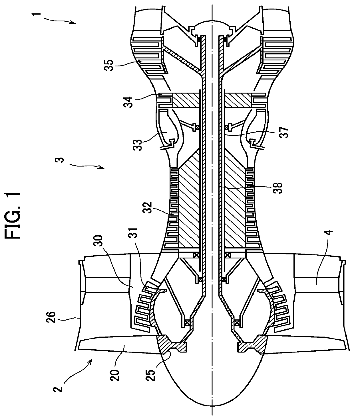
[0035]FIG. 1 is a schematic side sectional view of a general turbofan engine including fan blades.

[0036]A turbofan engine 1 is composed of a fan 2 that generates most of thrust, and a core engine 3 disposed coaxially with the fan 2 behind the fan 2, and including a turbine for driving the fan 2.

[0037]The core engine 3 is composed as a turbojet engine in which a low pressure compressor 31, a high pressure compressor 32, a combustor 33, a high pressure turbine 34, and a low pressure turbine 35 are disposed in order form an upstream side toward a downstream side. The high pressure turbine 34 is connected to the high pressure compressor 32 through a high pressure shaft 37, and the low pressure turbine 35 is connected to the low pressure compressor 31 and the fan 2 through a low pressure shaft 38.

[0038]The fan 2 includes a substantially cylindrical fan case 26, a fan disk...


PUM

PropertyMeasurementUnit
Thicknessaaaaaaaaaa

Abstract

Provided is a fan blade including an airfoil body composed of a composite material of thermoplastic resin or thermosetting resin and reinforcement fibers; a sheath made of metal that covers at least a part of a leading edge part of the airfoil body; and a guard made of metal that covers at least a part of a trailing edge part of the airfoil body, wherein a rear end part of the sheath and a front end part of the guard overlap in a thickness direction of the airfoil body on each plane of a pressure side and a suction side of the airfoil body, and the front end part of the guard is interposed between the rear end part of the sheath and the airfoil body in the overlapped section.

Description

TECHNICAL FIELD[0001]The present disclosure relates to a fan blade of a turbofan engine for an aircraft, and particularly relates to a fan blade made of a composite material.BACKGROUND ART[0002]A turbofan engine for an aircraft is composed of a fan, and a core engine disposed coaxially with the fan behind the fan, and including a turbine for driving the fan.[0003]The fan includes a substantially cylindrical fan case, and a fan disk formed to rotate inside the fan case, and a plurality of fan blades mounted on a circumference of the fan disk. The fan disk is rotationally driven by a low pressure turbine connected through a shaft.[0004]During operation of the turbofan engine, the fan blades rotate together with the fan disk, so that air is sucked by the fan. A part of the air flows into the core engine, high-temperature and high-pressure gas for driving the low pressure turbine is generated, and remaining air bypasses the core engine to be discharged from the back, and contributes to ...

Claims


Application Information

Patent Timeline
IPC IPC(8): F01D5/28F04D19/00B29C65/48B29C63/00B64F5/10
CPCB64C11/26F04D29/38F05D2220/36F01D5/147F01D21/08F01D5/282F05D2240/303F01D5/148F05D2300/501Y02T50/60F04D29/324F04D29/30B64F5/10B29C63/0026B29C65/48F01D5/28F04D19/002
Inventor OHBO, AKANEYAGI, HIROYUKI
Owner IHI CORP
Why Eureka
Try Eureka