Fuel injection device

Inactive Publication Date: 2019-11-28
HITACHI LTD
View PDF0 Cites 4 Cited by
  • Summary
  • Abstract
  • Description
  • Claims
  • Application Information

AI Technical Summary

Benefits of technology

[0012]According to the present invention, the fuel injection device capable of preventing generation of deposits in the injection hole and in the vicinity of the injection hole outlet, having no change in the spray pattern and the injection flow rate over time, and discharging fewer particula

Problems solved by technology

The deposit grows over time during use of the injection apparatus to eventually clog a part of the outlet of the injection nozzle, causing a change in a spray

Method used


Image

  • Fuel injection device
  • Fuel injection device
  • Fuel injection device

Examples


first embodiment

[0031]First, the structure of a first embodiment of the present invention will be described by referring to FIGS. 1 to 3.

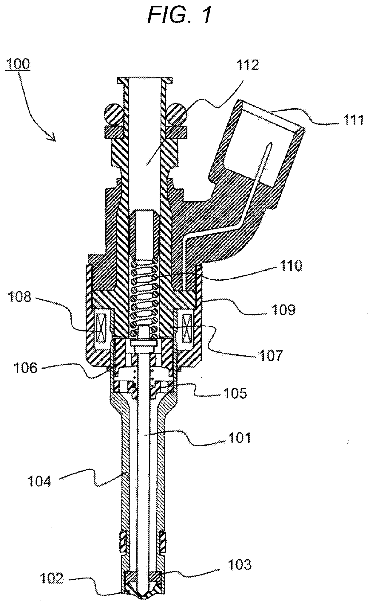
[0032]FIG. 1 is a cross-sectional view of an exemplary electromagnetic fuel injection device as an example of a fuel injection device according to the present embodiment. A basic operation of the injection device is described by referring to FIG. 1. In FIG. 1, fuel is supplied from a fuel supply inlet 112 to the interior of the fuel injection device. An electromagnetic fuel injection device 100 (which may also be called an electromagnetic fuel injection valve) illustrated in FIG. 1 is a normally-closed type electromagnetic-drive device in which a valve body 101 is biased by a spring 110, when a coil 108 is not energized, and pressed against an injection hole cup 102 which is bonded to a nozzle body 104 by welding or the like to seal the fuel. At this time, a fuel pressure supplied to the fuel injection device for cylinder injection is approximately in a range from...

second embodiment

[0050]FIG. 11 illustrates a second embodiment according to the present invention. In the present embodiment, as illustrated in the drawing, the radius decreases with distance from the injection hole cup 102. This increases the processing ability by rolling, pressing, and the like.

third embodiment

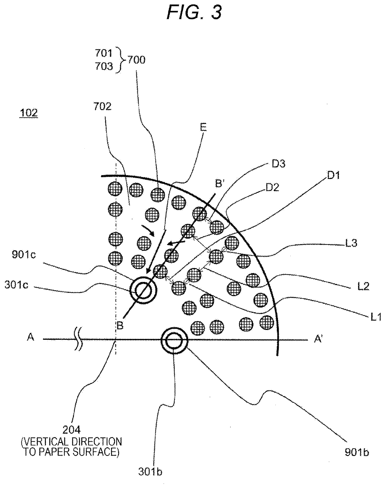
[0051]FIG. 12 illustrates a third embodiment according to the present invention. In the present embodiment, the lipophilic portion 701 and the low lipophilic portion 702 are formed by curved surfaces and are connected continuously. This increases a transfer speed of the fuel from the low lipophilic portion 702 to the lipophilic portion 701, and the deposit can be reduced. In the present embodiment, the lipophilic portion 701 is projecting, but may not be projecting and in, for example, a groove shape.


PUM


Abstract

It is possible to prevent a change in the spray pattern and injection flow rate and an increase of particulate matters in the exhaust gas due to residual fuel left in the vicinity of an injection hole outlet carbonized and adhered as deposit. A fuel injection valve includes a displaceable valve body, a valve seat surface that touches the valve body, and an injection hole cup including at least one injection hole formed on the valve body's tip end side and beyond where the valve seat surface touches the valve body. The injection hole cup includes a low lipophilic portion and a lipophilic portion formed on the injection hole cup's surface, the lipophilic portion is formed inside at least a part of a range in which the low lipophilic portion is formed, and at least one portion of the low lipophilic portion is connected to the injection hole's end portion.

Description

TECHNICAL FIELD[0001]The present invention relates to a fuel injection device used for an internal combustion engine, such as a gasoline engine, in which a valve touches a valve seat to prevent leakage of fuel and a valve moves away from the valve seat to allow injection.BACKGROUND ART[0002]In a fuel injection apparatus for vehicle engines, fuel left in the vicinity of an outlet of an injection nozzle is carbonized in or after injection of fuel, and the carbonized fuel is adhered as deposit. The deposit grows over time during use of the injection apparatus to eventually clog a part of the outlet of the injection nozzle, causing a change in a spray pattern or an injection flow rate. In addition, this deposit causes incomplete combustion and also causes an increase in particulate matters in the exhaust gas. Therefore, it is necessary to decrease the amount of the fuel left in the vicinity of the outlet of the injection nozzle in or after injection of the fuel.[0003]On the other hand, ...

Claims


Application Information

Patent Timeline
IPC IPC(8): F02M61/18B05B1/30
CPCF02M51/061F02M61/20F02M2200/06F02M61/1886F02M61/042F02M2200/90B05B1/3053F02M61/166F02M61/1833
Inventor SUGII, TAISUKEISHII, EIJIYOSHIMURA, KAZUKIHOSAKA, TOMOYUKI
Owner HITACHI LTD
Why Eureka
Try Eureka