Portable ultrasound system

a portable ultrasound and ultrasound technology, applied in the field of portable ultrasound systems, can solve the problems of ultrasound system use of touchscreen display control functions, and achieve the effects of minimizing the overall packaging size and footprint, reducing the size of the circuit board, and high channel coun

Pending Publication Date: 2019-12-05
TERATECH CORP
View PDF4 Cites 25 Cited by
  • Summary
  • Abstract
  • Description
  • Claims
  • Application Information

AI Technical Summary

Benefits of technology

[0006]Touchscreen embodiment can recognize and distinguish one or more single, multiple, and / or simultaneous touches on a surface of the touch screen display, thereby allowing the use of gestures, ranging from simple single point gestures to complex multipoint moving gestures, as user inputs to the medical ultrasound imaging equipment.
[0009]In accordance with an exemplary aspect, at least one flick gesture may be employed to control the depth of tissue penetration of ultrasound waves generated by the ultrasound probe / transducer. For example, a single flick gesture in the “up” direction on the touch screen display surface can increase the penetration depth by one (1) centimeter or any other suitable amount, and a single flick gesture in the “down” direction on the touch screen display surface can decrease the penetration depth by one (1) centimeter or any other suitable amount. Further, a drag gesture in the “up” or “down” direction on the touch screen display surface can increase or decrease the penetration depth in multiples of one (1) centimeter or any other suitable amount. Additional operational modes and / or functions controlled by specific single point / multipoint gestures on the touch screen display surface can include, but are not limited to, freeze / store operations, 2-dimensional mode operations, gain control, color control, split screen control, PW imaging control, cine / time-series image clip scrolling control, zoom and pan control, full screen control, Doppler and 2-dimensional beam steering control, and / or body marking control. At least some of the operational modes and / or functions of the exemplary medical ultrasound imaging equipment can be controlled by one or more touch controls implemented on the touch screen display in which beamforming parameters can be reset by moving touch gestures. Medical personnel can provide one or more specific single point / multipoint gestures as user inputs for specifying at least one selected subset of the touch controls to be implemented, as required and / or desired, on the touch screen display. A larger number of touchscreen controls enable greater functionality when operating in full screen mode when a few or more virtual buttons or icons are available for use.
[0011]By providing medical ultrasound imaging equipment with a multi-touch touchscreen, medical personnel can control the equipment using simple single point gestures and / or more complex multipoint gestures, without the need of a traditional keyboard or knob. Because the multi-touch touch screen obviates the need for a traditional keyboard or knob, such medical ultrasound imaging equipment is easier to keep clean in hospital and / or field environments, provides an intuitive user friendly interface, while providing fully functional operations. Moreover, by providing such medical ultrasound imaging equipment in a tablet form factor, medical personnel can easily transport the equipment between hospital and / or field locations.
[0015]The term “multi-chip module,” as used herein, refers to an electronic package in which multiple integrated circuits (IC) are packaged with a unifying substrate, facilitating their use as a single component, i.e., as a higher processing capacity IC packaged in a much smaller volume. Each IC can comprise a circuit fabricated in a thinned semiconductor wafer. Exemplary embodiments also provide an ultrasound engine including one or more such multi-chip modules, and a portable medical ultrasound imaging system including an ultrasound engine circuit board with one or more multi-chip modules. Exemplary embodiments also provide methods for fabricating and assembling multi-chip modules as taught herein. Vertically stacking the TR chip, the pre-amp / TGC chip, and the beamformer chip on a circuit board minimizes the packaging size (e.g., the length and width) and the footprint occupied by the chips on the circuit board.
[0017]Exemplary numbers of chips vertically integrated in a multi-chip module may include, but are not limited to, two, three, four, five, six, seven, eight, and the like. In one embodiment of an ultrasound device, a single multi-chip module is provided on a circuit board of an ultrasound engine that performs ultrasound-specific operations. In other embodiments, a plurality of multi-chip modules are provided on a circuit board of an ultrasound engine. The plurality of multi-chip modules may be stacked vertically on top of one another on the circuit board of the ultrasound engine to further minimize the packaging size and the footprint of the circuit board.
[0018]Providing one or more multi-chip modules on a circuit board of an ultrasound engine achieves a high channel count while minimizing the overall packaging size and footprint. For example, a 128-channel ultrasound engine circuit board can be assembled, using multi-chip modules, within exemplary planar dimensions of about 10 cm×about 10 cm, which is a significant improvement over the much larger space requirements of conventional ultrasound circuits. A single circuit board of an ultrasound engine including one or more multi-chip modules may have 16 to 128 channels in some embodiments. In certain embodiments, a single circuit board of an ultrasound engine including one or more multi-chip modules may have 16, 32, 64, 128 or 192 channels, and the like.

Problems solved by technology

Consequently, it is highly desirable to provide a portable ultrasound device that can be used by gloved hands; however, this has previously prevented the use of touchscreen display control functions in ultrasound systems for many applications requiring sterile precautions.

Method used


Image

  • Portable ultrasound system
  • Portable ultrasound system
  • Portable ultrasound system

Examples


Embodiment Construction

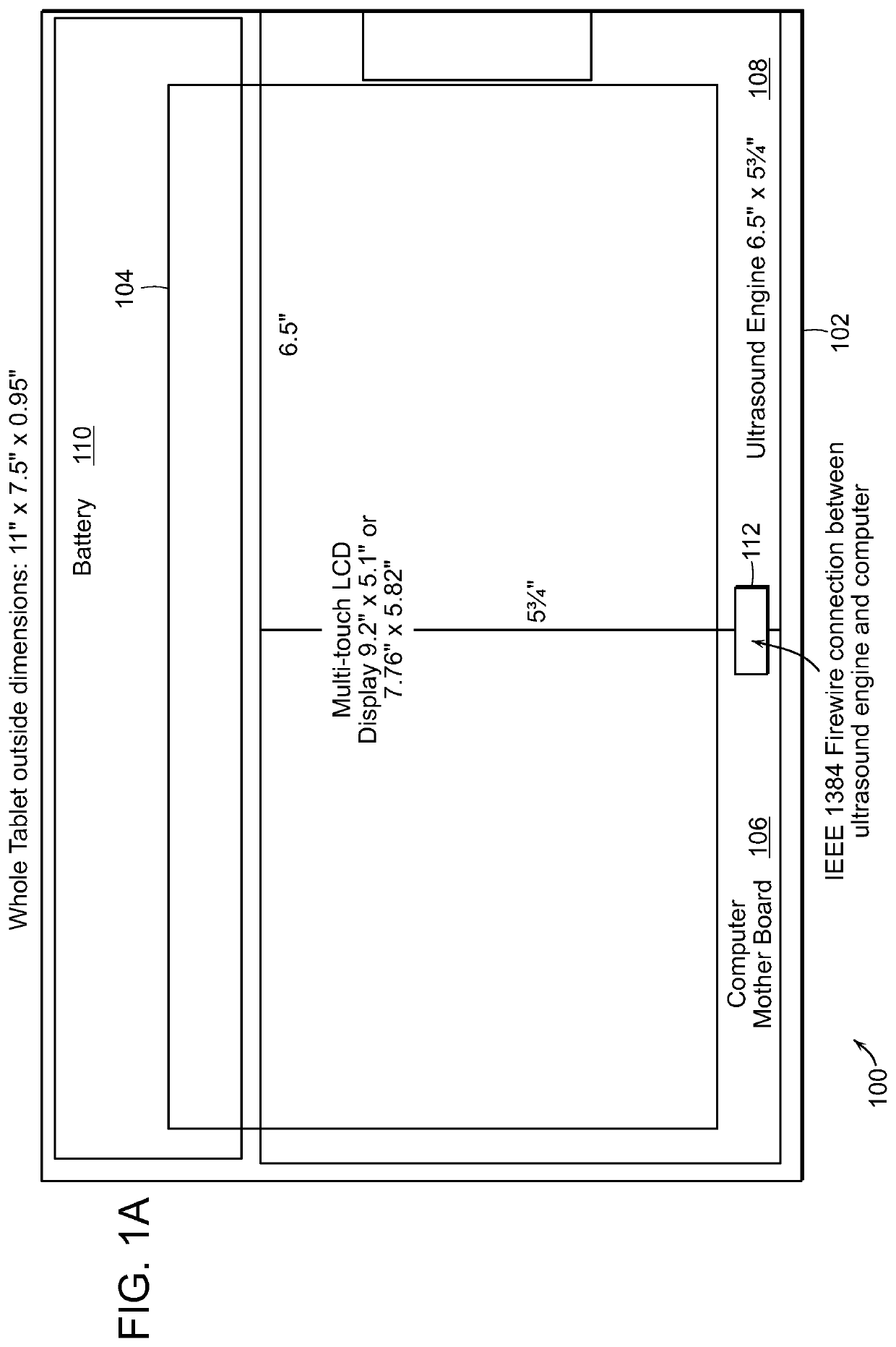
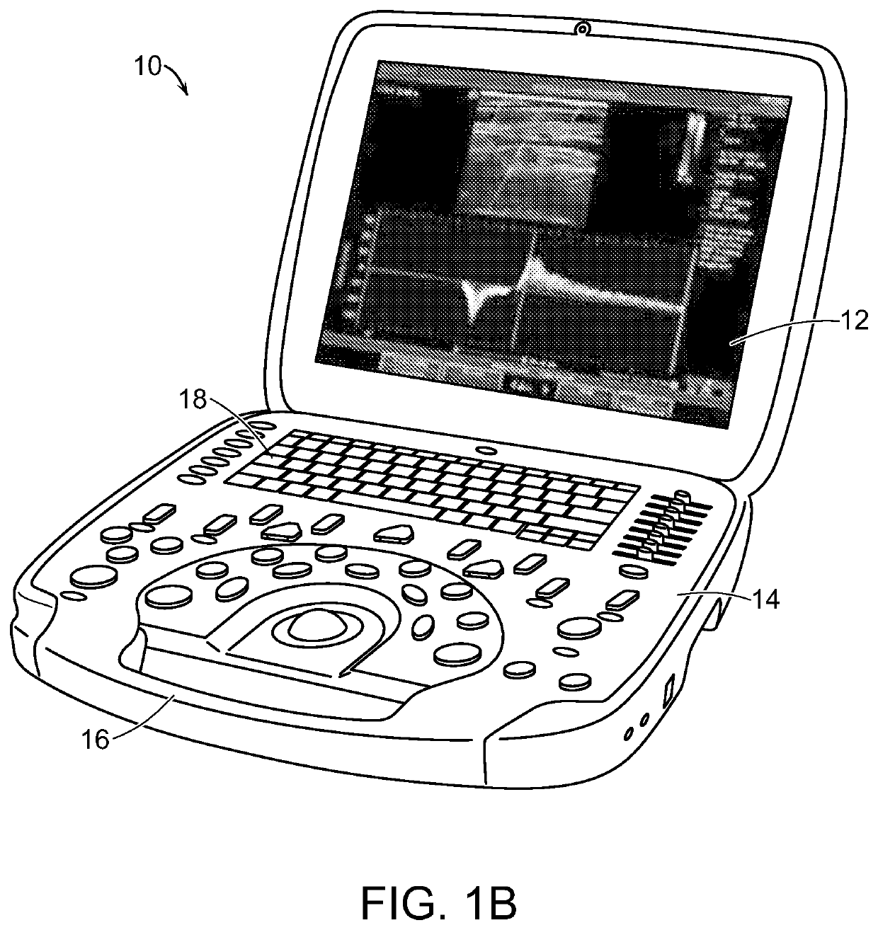
[0106]Systems and methods of medical ultrasound imaging are disclosed. The presently disclosed systems and methods of medical ultrasound imaging employ medical ultrasound imaging equipment that includes housing in a tablet form factor, and a touch screen display disposed on a front panel of the housing. The touch screen display includes a multi-touch touch screen that can recognize and distinguish one or more single, multiple, and / or simultaneous touches on a surface of the touch screen display, thereby allowing the use of gestures, ranging from simple single point gestures to complex multipoint gestures, as user inputs to the medical ultrasound imaging equipment. Further details regarding tablet ultrasound systems and operations are described in U.S. application Ser. No. 10 / 997,062 filed on Nov. 11, 2004, Ser. No. 10 / 386,360 filed Mar. 11, 2003 and U.S. Pat. No. 6,969,352, the entire contents of these patents and applications are incorporated herein by reference.

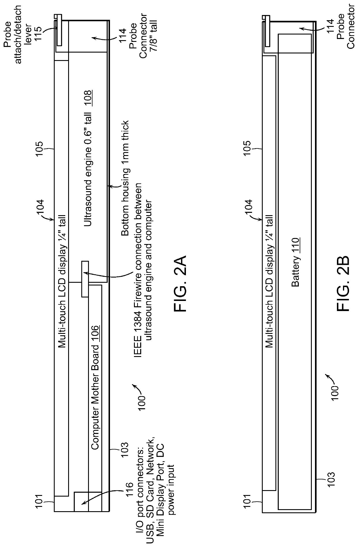
[0107]FIGS. 1A and ...


PUM


Abstract

Exemplary embodiments provide systems and methods for portable medical ultrasound imaging. Preferred embodiments utilize a hand portable, battery powered system having a display and a user interface operative to control imaging and display operations. A keyboard control panel can be used alone or in combination with touchscreen controls to actuate a graphical user interface. Exemplary embodiments also provide an ultrasound engine circuit board including one or more multi-chip modules, and a portable medical ultrasound imaging system including an ultrasound engine circuit board.

Description

CROSS REFERENCE TO RELATED APPLICATIONS[0001]This application claims priority to U.S. Application No. 62 / 565,846 filed on Sep. 29, 2017 and to U.S. Application No. 62 / 422,808 filed Nov. 16, 2016, which is a continuation-in-part of U.S. application Ser. No. 15 / 025,058 filed on Sep. 25, 2014 and is also a continuation-in-part of U.S. application Ser. No. 14 / 037,106 filed Sep. 25, 2013, which claims priority to International Application PCT / US2013 / 033941 filed Mar. 26, 2013, and U.S. application Ser. No. 13 / 838,694 filed Mar. 15, 2013, and to U.S. Provisional Application No. 61 / 615,627, filed Mar. 26, 2012 and U.S. Provisional Application No. 61 / 704,254, filed Sep. 21, 2012, these applications being incorporated herein by reference in their entirety.BACKGROUND OF THE INVENTION[0002]Medical ultrasound imaging has become an industry standard for many medical imaging applications. In recent years, there has been an increasing need for medical ultrasound imaging equipment that is portable ...

Claims


Application Information

Patent Timeline
Patent Type & Authority Applications(United States)
IPC IPC(8): A61B8/00
CPCA61B8/488A61B8/4433H01L2224/73265H01L2924/181H01L2224/32145A61B8/4427A61B8/461G06F3/0481A61B8/469H01L2224/48247A61B8/12G06F3/04842A61B8/4405A61B8/465G06F3/04886H01L2224/32245H01L2224/48091H01L2924/00014H01L2924/00012
Inventor CHIANG, ALICE M.
Owner TERATECH CORP
Why Eureka
Try Eureka