System and method for camera calibration
a camera and calibration technology, applied in the field of diagnostic imaging, can solve the problems of difficult diagnosis of certain skin cancer types, conservative approach to making more biopsies, and inconvenient geometry, etc., and achieve the effects of accurate determination, better suitable geometry, and high sensitivity
- Summary
- Abstract
- Description
- Claims
- Application Information
AI Technical Summary
Benefits of technology
Problems solved by technology
Method used
Image
Examples
first embodiment
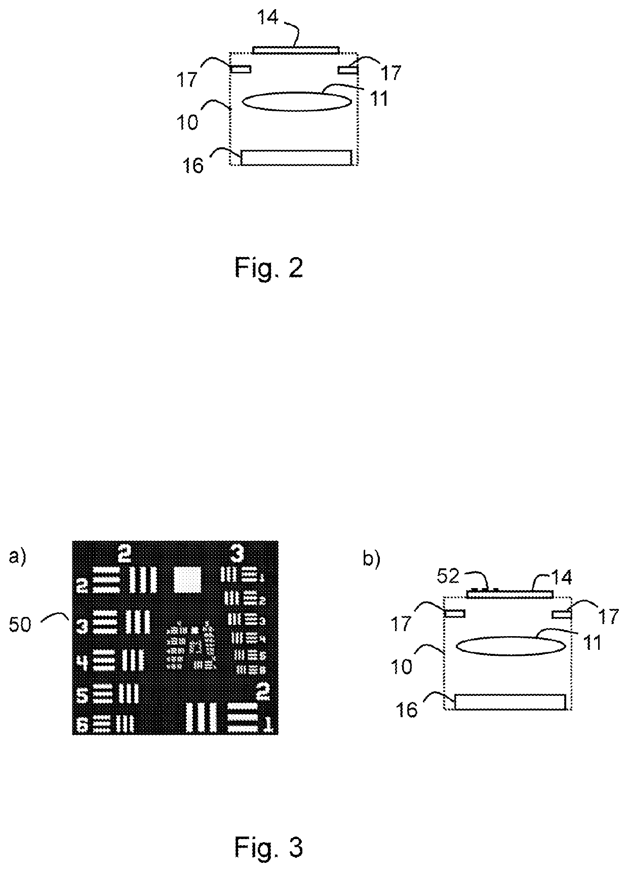
[0115]In the first embodiment according to the present invention, in order to calibrate the focusing means by controlling the position of the focus at a given wavelength, a calibration pattern may be positioned at a known position along the optical axis of the image acquisition device, e.g. sensor and within its field of view. The pattern can for example be placed at the edge of the FOV so as not to disturb the images. The images presented to the users may even not comprise the image of the calibration pattern so as not to disturb the user, but only the central part, comprising the object of interest.
[0116]As the focus position or focal length can depend on the wavelength, each light source, having a different spectral bandwidth centered on a different wavelength will in this case have different focus positions for a same configuration of the device (same curvature of the liquid lens or same position of the image acquisition device), or a different configuration for a same focus pos...
second embodiment
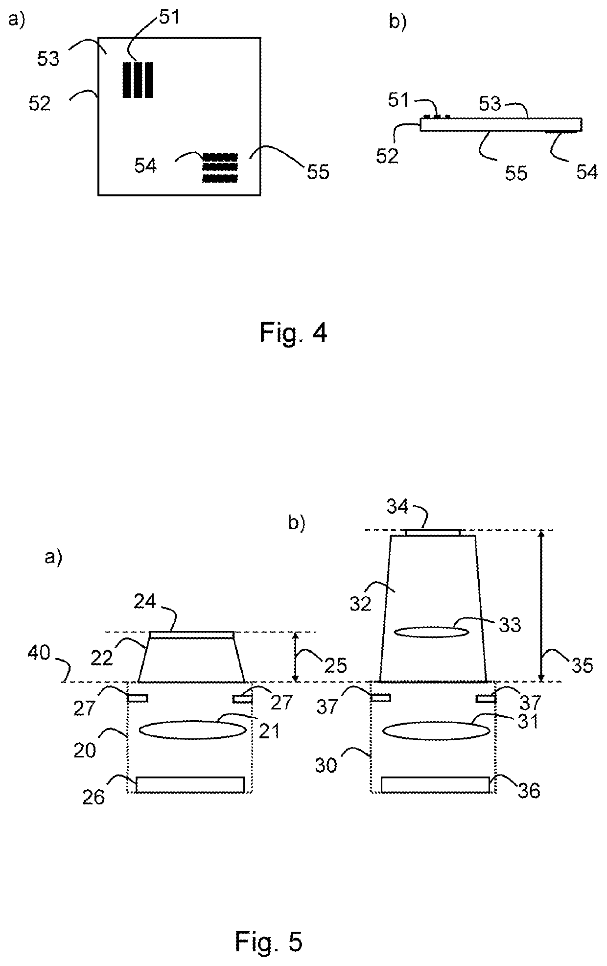
[0127]In the present invention, a second pattern is provided on or in the front glass as the reference viewing surface at a distance from the first pattern. For example, this can be implemented by providing the patterns on the upper and lower surfaces of the front glass, in which case they are separated by the thickness of the glass. FIG. 4 shows a) a top view and b) a side view of two patterns arranged at opposite sides of the front glass. A pattern 51 is provided on the upper surface of a front glass 52 on the front side 53. Another pattern 54 is put on the back side 55 of the front glass 52. By knowing the thickness of the glass it is possible to establish a relationship between the positions of the patterns 51 and 54 and the digital driving levels, assuming linearity of the system or a known / pre-defined / approximated non-linear behavior of the system. With this knowledge it is possible to steer the image acquisition device, e.g. camera to focus on a specific depth in the sample, ...
third embodiment
[0135]In a third embodiment according to the present invention there is foreseen an additional three-dimensional calibration piece which is put in front of the front glass as reference viewing surface. The three-dimensional calibration piece can be any substrate, such as glass, plastic, etc. It can be transparent but this is not a requirement as it is removed when real measurements are performed. The pattern comprises a physical structure that is provided at a variety of known depths within the calibration piece (that can exceed the thickness of the front glass). A simple solution can for example be a substrate with straight parallel lines, which are in a plane which is tilted with respect to the plane of the image acquisition device, e.g. camera sensor. FIG. 7 illustrates an exemplary embodiment comprising a pattern 61 having parallel lines extending at different depths (z direction) of the substrate, the z direction corresponding to the optical axis of the device. The sample can b...
PUM
 Abstract
Description
Claims
Application Information
 - R&D
- Intellectual Property
- Life Sciences
- Materials
- Tech Scout
- Unparalleled Data Quality
- Higher Quality Content
- 60% Fewer Hallucinations
Browse by: Latest US Patents, China's latest patents, Technical Efficacy Thesaurus, Application Domain, Technology Topic, Popular Technical Reports.
© 2025 PatSnap. All rights reserved.Legal|Privacy policy|Modern Slavery Act Transparency Statement|Sitemap|About US| Contact US: help@patsnap.com


