

Device and Method for Fusing Image Data from a Multi-Camera System for a Motor Vehicle
Patent Information
- Authority / Receiving Office
- US · United States
- Current Assignee / Owner
- CONTI TEMIC MICROELECTRONIC GMBH
- Publication Date
- 2019-12-26
- Estimated Expiration
- Not applicable · inactive patent
Smart Images
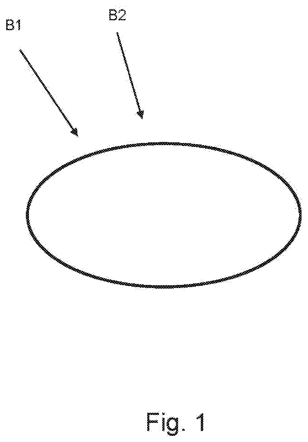
Figure 1 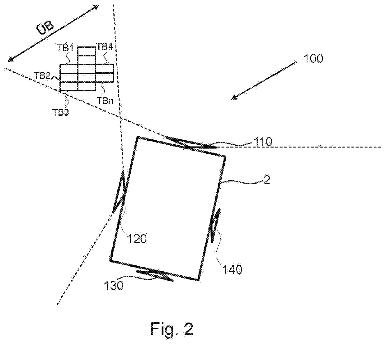
Figure 2 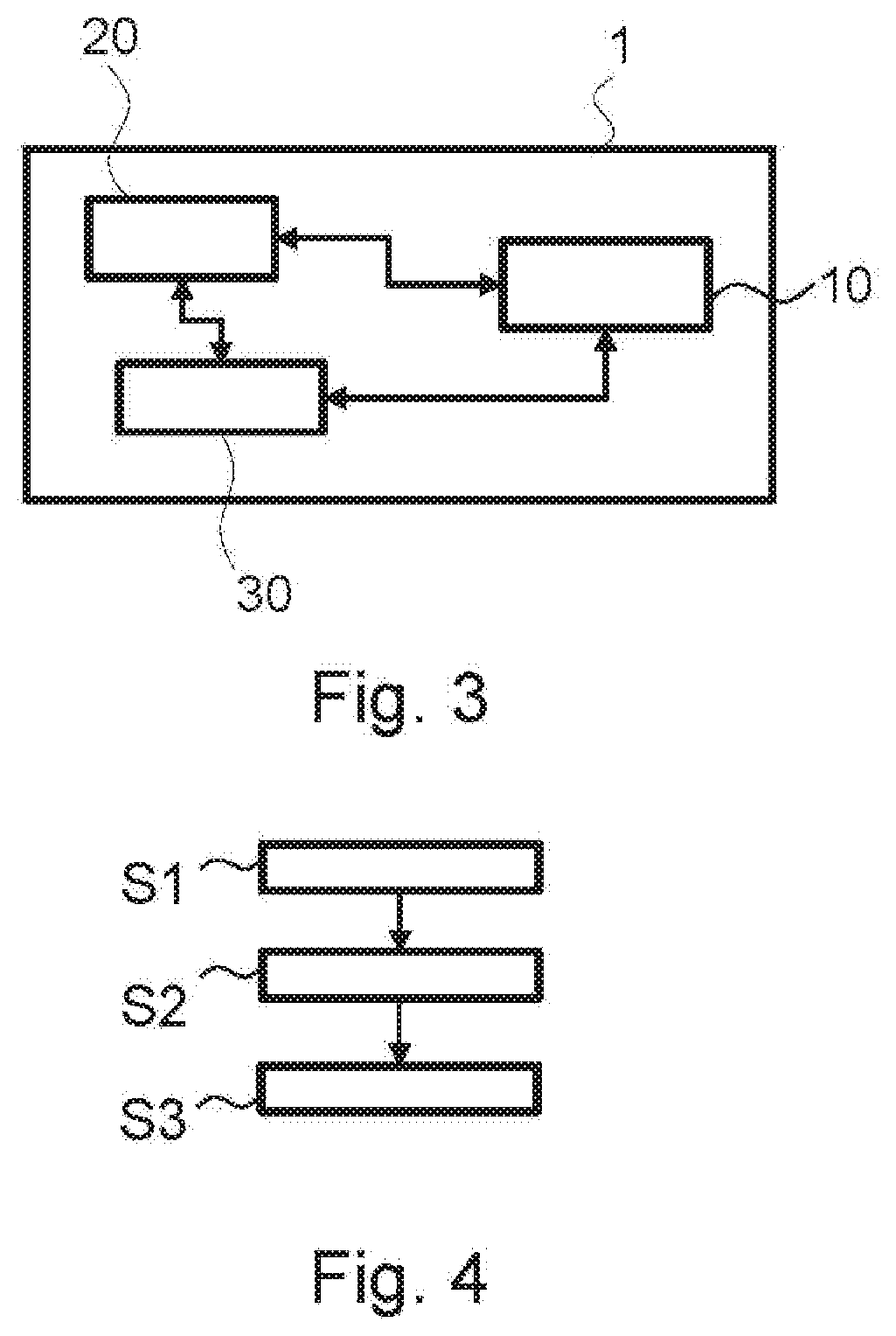
Figure 3
Abstract
Description
TECHNICAL FIELD
[0001] The present invention relates to image processing systems for driver assistance systems for motor vehicles.
[0002] In particular, the present invention relates to a device and a method for fusing image data from a multi-camera system for a motor vehicle.TECHNICAL BACKGROUND
[0003] Multi-camera systems in motor vehicles constitute an enhanced acquisition of the surrounding area compared with what would be possible with a single camera.
[0004] Multi-camera systems are mostly installed in motor vehicles such that camera constellations with overlapping views are created.
[0005] In today's vehicle-based surround view systems, the overlapping fields of view of the adjacent cameras which occur are frequently already manually configured during the production of the motor vehicle.
[0006] The disadvantage is that this always requires a manual configuration for each vehicle variant and is therefore rather time-consuming and costly.
[0007] The manual configuration results in a sudden a...