
Increasing bandwidth of a dipole antenna

Active Publication Date: 2019-12-26
K N TOOSI UNIV OF TECH +2
View PDF0 Cites 2 Cited by
  • Summary
  • Abstract
  • Description
  • Claims
  • Application Information

AI Technical Summary

Benefits of technology

The present patent describes an improved dipole antenna design that includes a coaxial feed line and a conductive shield. This design helps to improve the performance of the antenna and make it more efficient in transmitting signals. The antenna also includes a ferrite sleeve that helps to reduce interference and improve the quality of the signal transmission. The technical effects of this design allow for improved reliability and performance of the dipole antenna in various applications.

Problems solved by technology

Therefore, designing a portable and small size dipole antenna in low-frequency bands (such as VHF and UHF bands) may be challenging due to large wavelengths corresponding to low-frequency bands.
A problem of dipole antennas may be their relatively narrow impedance bandwidth.
This approach may be undesired because it may increase sizes of dipole antennas.
Besides, sizes of dipole antennas may have a limited effect on bandwidth.
However, utilizing these techniques may increase complexity, cost, and size of dipole antennas.

Method used


Image

  • Increasing bandwidth of a dipole antenna
  • Increasing bandwidth of a dipole antenna
  • Increasing bandwidth of a dipole antenna

Examples


example

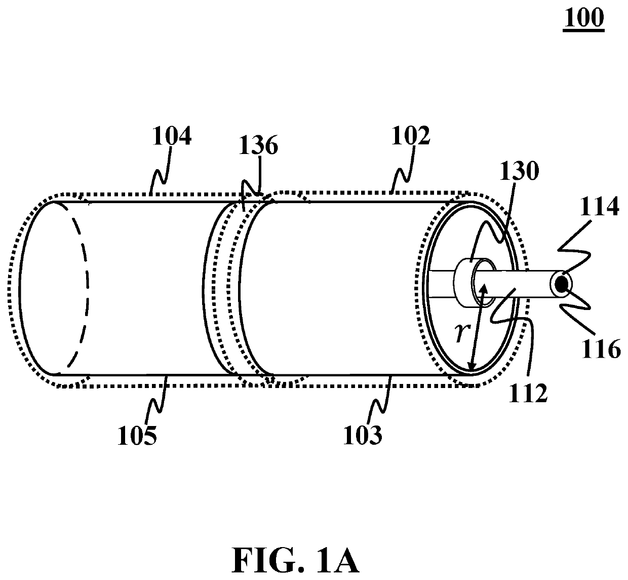
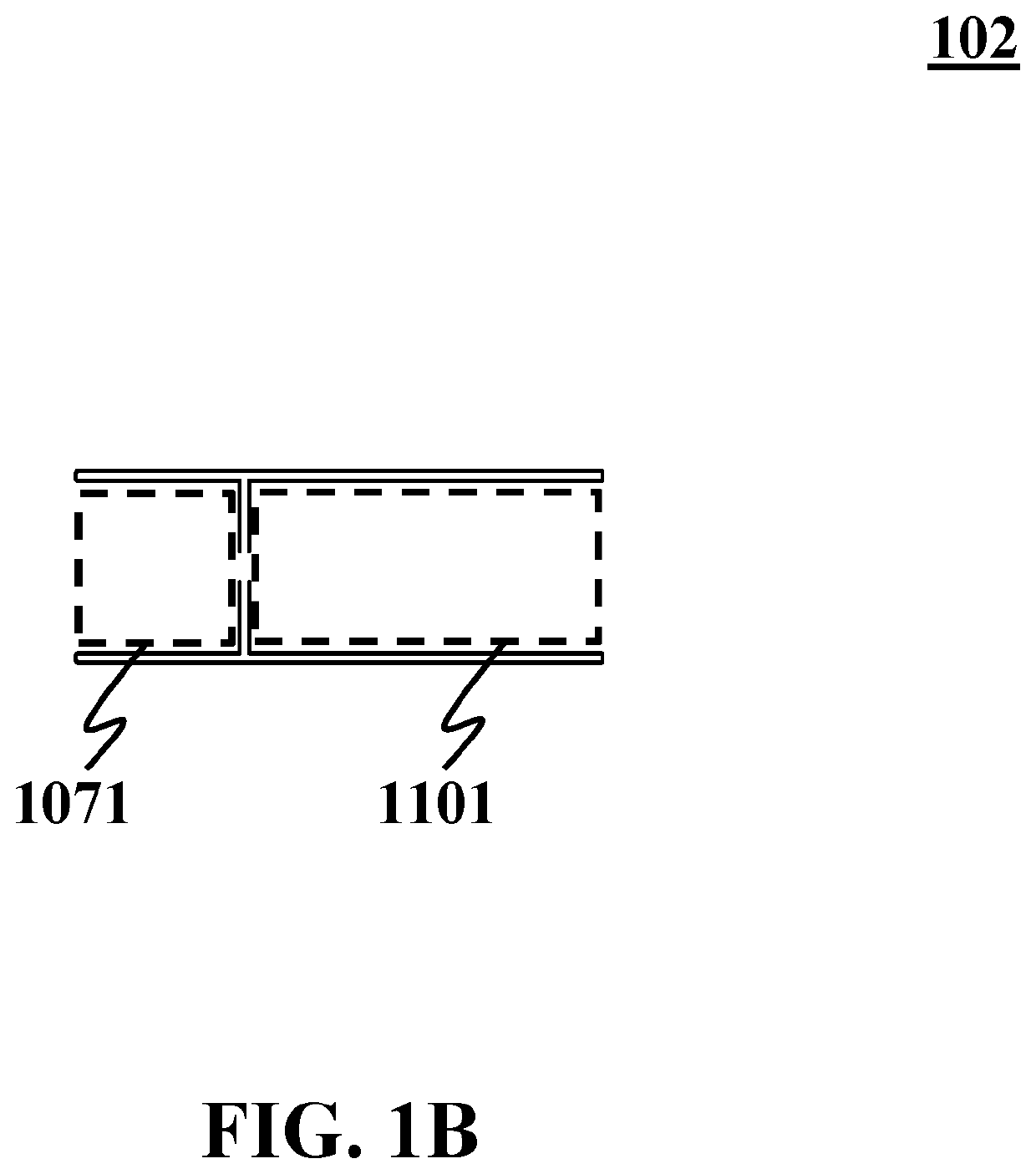
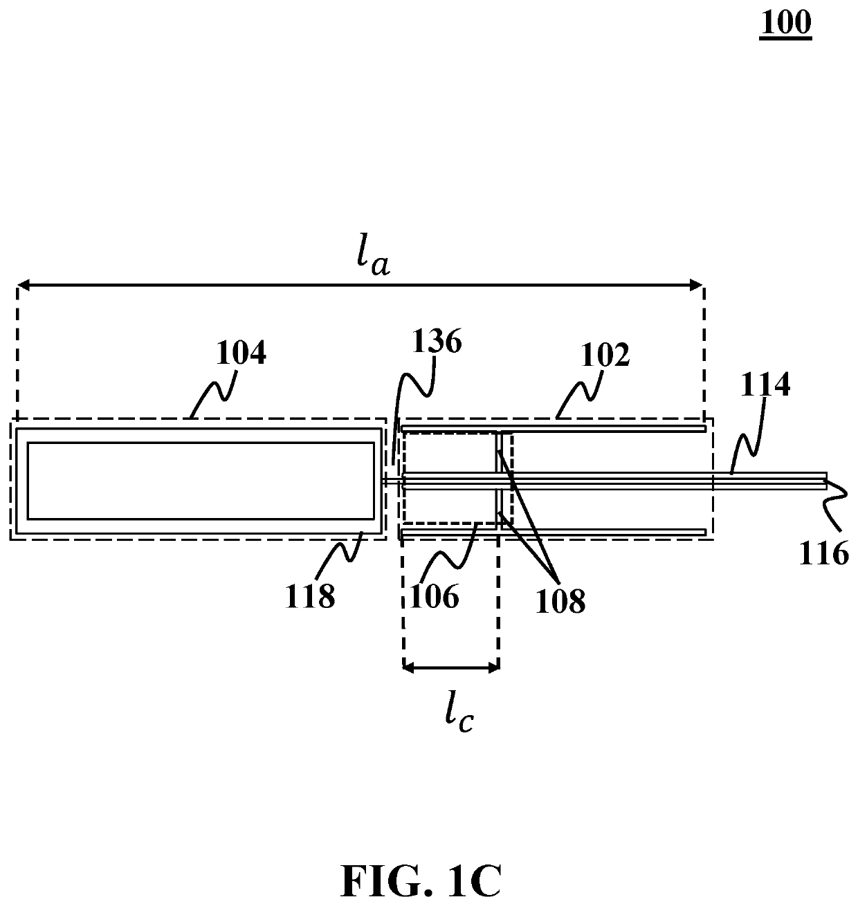
[0055]In this example, a dipole antenna including a first arm and a second arm with a cavity inside the first arm is demonstrated. An exemplary dipole antenna (analogous to dipole antenna 100) includes a first arm (analogous to first arm 102) and the second arm (analogous to second arm 104). The dipole antenna is designed for a desired band of 300 MHz to 400 MHz. The first arm and the second arm of the dipole antenna have a cylindrical body with a radius of about 25 mm. The first arm includes a cavity (analogous to cavity 106) that has a length about 25 mm and a remaining of the first arm (analogous to remaining 1101 of first arm 102 having a length about 140 mm. The total length of the first arm is about 165 mm. The second arm of the dipole antenna has a length of about 195 mm. The first arm and the second arm are spaced by an air gap (analogous to air gap 136) having a length about 7 mm. The total length of the antenna is about 367 mm which is about 0.367 of a maximum operating wa...


PUM


Abstract

A dipole antenna is disclosed. The dipole antenna includes a first arm, a second arm, and a first conductive plate. The first conductive plate is placed inside one of the first arm or the second arm. The first conductive plate creates a cavity inside the one of the first arm or the second arm.

Description

CROSS-REFERENCE TO RELATED APPLICATION[0001]This application claims the benefit of priority from pending U.S. Provisional Patent Application Ser. No. 62 / 723,491, filed on Aug. 28, 2018, and entitled “A SIMPLE AND EFFECTIVE METHOD TO INCREASE DIPOLE ANTENNA'S BANDWIDTH,” which is incorporated herein by reference in its entirety.TECHNICAL FIELD[0002]The present disclosure generally relates to antennas, and particularly, to dipole antennas.BACKGROUND[0003]Dipole antennas are a type of wired antennas for wireless communication systems that have specific characteristics such as omnidirectional radiation patterns. Lengths of conventional dipole antennas may be about half of operating wavelengths. Designing dipole antennas with a smaller size may reduce gain or bandwidth. Therefore, designing a portable and small size dipole antenna in low-frequency bands (such as VHF and UHF bands) may be challenging due to large wavelengths corresponding to low-frequency bands.[0004]A problem of dipole a...

Claims


Application Information

Patent Timeline
IPC IPC(8): H01Q9/22
CPCH01Q9/22H01Q5/50H01Q9/16H01Q9/20H01Q9/24H01Q9/265
Inventor ALIAKBARIAN, HADISAHRAEI, AMIR
Owner K N TOOSI UNIV OF TECH
Learn More