
Method and system for measuring the laxity of a joint of a human or an animal

Pending Publication Date: 2020-01-02
AALBORG UNIV
View PDF3 Cites 2 Cited by
  • Summary
  • Abstract
  • Description
  • Claims
  • Application Information

AI Technical Summary

Benefits of technology

The invention relates to a system and method for accurately measuring the movement and stability of joints in a person or animal. The system uses a slot scanner, such as an EOS scanner, which exposes the joint to a lower dose of X-ray radiation than traditional X-rays. The sales of EOS system are increasing because it provides low dose, partly or full body, stereo-radiographic images of a patient. The system can obtain more accurate measurements and reduce the risk of negative influences on the health of the person or animal being investigated.

Problems solved by technology

However, this kind of method has been shown to not lead to accurate estimates of the laxity as the soft tissue around the joints and bones means that the skin measurements do not correctly reflect the bone movements.
Furthermore, it is typically limited to only one and two directions, which is not always sufficient.
However, an MRI scan typically takes several minutes during which period of time the person being investigated must lay completely still.
This leads to long measurement periods since one MRI scan must be obtained for each loading that is assessed.
Furthermore, this scanning method does not allow metallic parts around the patient which prohibits its use for post-operative assessment following implantation of metal implants.
However, it is well-known that the exposure to X-ray radiation should be minimised as it may cause health risks.
Therefore, this method is not optimal for a prolonged or repeated assessment.
A further challenge with this technique is to avoid undesired interference between a loading device and the X-rays.
However, this approach is invasive and, therefore, not applicable in daily clinical examination.

Method used


Image

  • Method and system for measuring the laxity of a joint of a human or an animal
  • Method and system for measuring the laxity of a joint of a human or an animal
  • Method and system for measuring the laxity of a joint of a human or an animal

Examples


Embodiment Construction

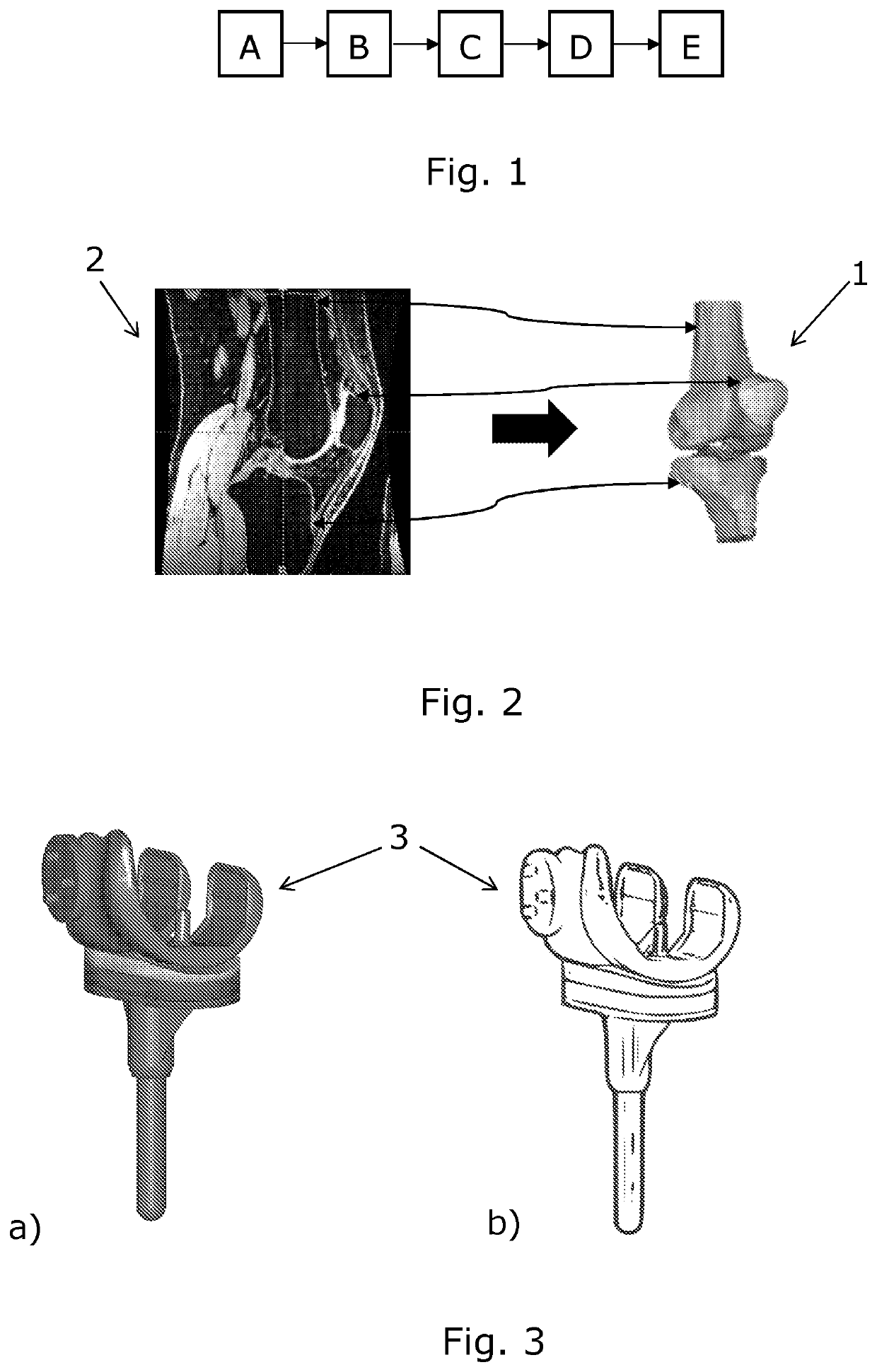
[0066]FIG. 1 schematically shows a flow-chart of the method of determining the laxity of a joint of a human or an animal according to the present invention; more details of the method steps will be given in the following figures. The method comprises the following steps which will be described in details below:[0067](A) providing at least one patient-specific geometrical model of at least one bone and / or at least one prosthesis comprised by the joint,[0068](B) providing a series of actual images of the joint obtained while known loads were applied to the joint or to a part of the body connected to the joint,[0069](C) registering the at least one patient-specific geometrical model onto the actual images,[0070](D) based thereon calculate relative displacement and / or rotation of the at least one bone and / or at least one prosthesis as a function of the applied loads, and[0071](E) based on the calculated relative displacement and / or rotation determine a measure of the laxity of the joint...


PUM


Abstract

The invention relates to a method of determining the laxity of a joint (9, 15) of a human (5) or an animal. The method comprises providing at least one patient-specific geometrical model (1) of at least one bone and / or at least one prosthesis comprised by the joint. Known loads are applied to the joint or to a part of the body connected to the joint, and a series of actual images (16) of the joint are obtained while the loads are applied. Then the at least one patient-specific geometrical model (1) is registered onto the actual images (16). Based thereon relative displacement and / or rotation of the at least one bone and / or at least one prosthesis is calculated as a function of the applied loads, and based thereon a measure of the laxity of the joint is determined. The invention further relates to a system for performing such a method and to a computer readable medium for performing such a method.

Description

FIELD OF THE INVENTION[0001]The present invention relates to the determination of the laxity of a joint of a human or an animal, and in particular to such determination which can be performed in a well-defined and reproducible way.BACKGROUND OF THE INVENTION[0002]The ligaments of a joint play a critical role in stabilizing the joint. The stability of the joint, also referred to as the joint laxity, is therefore an indicator of the functioning of the ligaments. In order to assess the ligaments for injury, plan treatment or follow up after intervention, information about the laxity of the joint is therefore important. Such an evaluation of the laxity of a joint is also relevant e.g. during the process of the implementation of a knee prosthesis or the replacement of ligaments. In practise, this evaluation is often done by a doctor manually applying a force to a part of the body connected to the joint and manually sensing the resulting movement of the joint. However, such a determinatio...

Claims


Application Information

Patent Timeline
IPC IPC(8): A61B5/00A61B5/11A61B5/055A61B6/03A61B8/08
CPCA61B6/032A61B8/5207A61B5/0048A61B5/1121A61B5/4528A61B5/055A61B5/1071A61B5/4504A61B2034/105
Inventor ANDERSEN, MICHAEL SKIPPERSTOLTZE, JONAS STENSGAARDPEDERSEN, DENNIS
Owner AALBORG UNIV
Features
  • Generate Ideas
  • Intellectual Property
  • Life Sciences
  • Materials
  • Tech Scout
  • Unparalleled Data Quality
  • Higher Quality Content
  • 60% Fewer Hallucinations
Learn More