Artificial lens capsule

a technology of artificial lens capsules and capsules, applied in the field of ophthalmic surgery, can solve the problems of inability to fix by such alternative methods, and inability to fix by such alternative methods, and achieve the effects of simple device structure, excellent deformation, and simplified structur

Pending Publication Date: 2020-01-02
KYOTO PREFECTURAL PUBLIC UNIV CORP
View PDF3 Cites 6 Cited by
  • Summary
  • Abstract
  • Description
  • Claims
  • Application Information

AI Technical Summary

Benefits of technology

[0023]The present invention has the following effects.
[0024]Since the intraocular lens fixing device of the invention has a frame with a shape that conforms to a ciliary sulcus, the device of the invention can be fixed inside an eye with a ruptured or lost lens capsule, and can house and fix any type of intraocular lens in an intraocular lens housing of the device. The device structure can also be simplified and has excellent deformability. Since a frame is used to fix a device to a ciliary sulcus, the structure can also be simplified to reduce manufacturing cost.
[0025]Furthermore, if an intraocular lens housing is configured to have a bag portion with an inner cavity formed thereon to be able to store an intraocular lens rotatably about the visual axis in the bag portion, the intraocular lens can be rotated within the bag portion of the housing to change the fixation angle so as to correct the astigmatic axis of a patient when fixing an astigmatism corrective intraocular lens with an additional function of astigmatism correction with the device.
[0026]The present invention attains an improved effect over conventional intraocular lens fixing devices.
[0027]For example, many conventionally proposed devices are embedded into the lens capsule, but the prevent invention is advantageous over such devices in that the invention can be applied inside an eye with a ruptured or lost lens capsule.
[0028]For devices that can be applied inside an eye with a ruptured or lost lens capsule, optical parts used in the devices have a specific shape to conform to the devices so that various types of intraocular lenses depicted in FIGS. 14 and 15 cannot be fixed to the devices, but the present invention is also compatible with such shapes. Especially when an astigmatism correction lens is fixed inside an eye, a lens needs to be fixed to a device in a direction matching the direction of astigmatism by rotating the astigmatism correction lens about the visual axis as described above. Meanwhile, conventional devices cannot rotatably store an intraocular lens, and an intraocular lens can also shift after fixing the lens to the device, but this has been overcome by the present invention. Furthermore, a multifocal intraocular lens cannot be suitably fixed inside a device for a configuration where an intraocular lens moves in the direction of the visual axis inside the device. A device provided with a fixing support also has a risk of damaging tissue when inserting the device into an eye, and the structure of such a device is complex with high manufacturing cost. Meanwhile, the present invention is advantageous in that this can also be addressed.

Problems solved by technology

However, astigmatism correction lenses and multifocal intraocular lenses, which can be fixed with normal intracapsular fixation, cannot be fixed by such alternative methods.
It is also very technically complex and difficult to fix the lens 3 after rotating the lens to a direction matching the astigmatism around the visual axis.

Method used


Image

  • Artificial lens capsule
  • Artificial lens capsule
  • Artificial lens capsule

Examples


embodiment 1

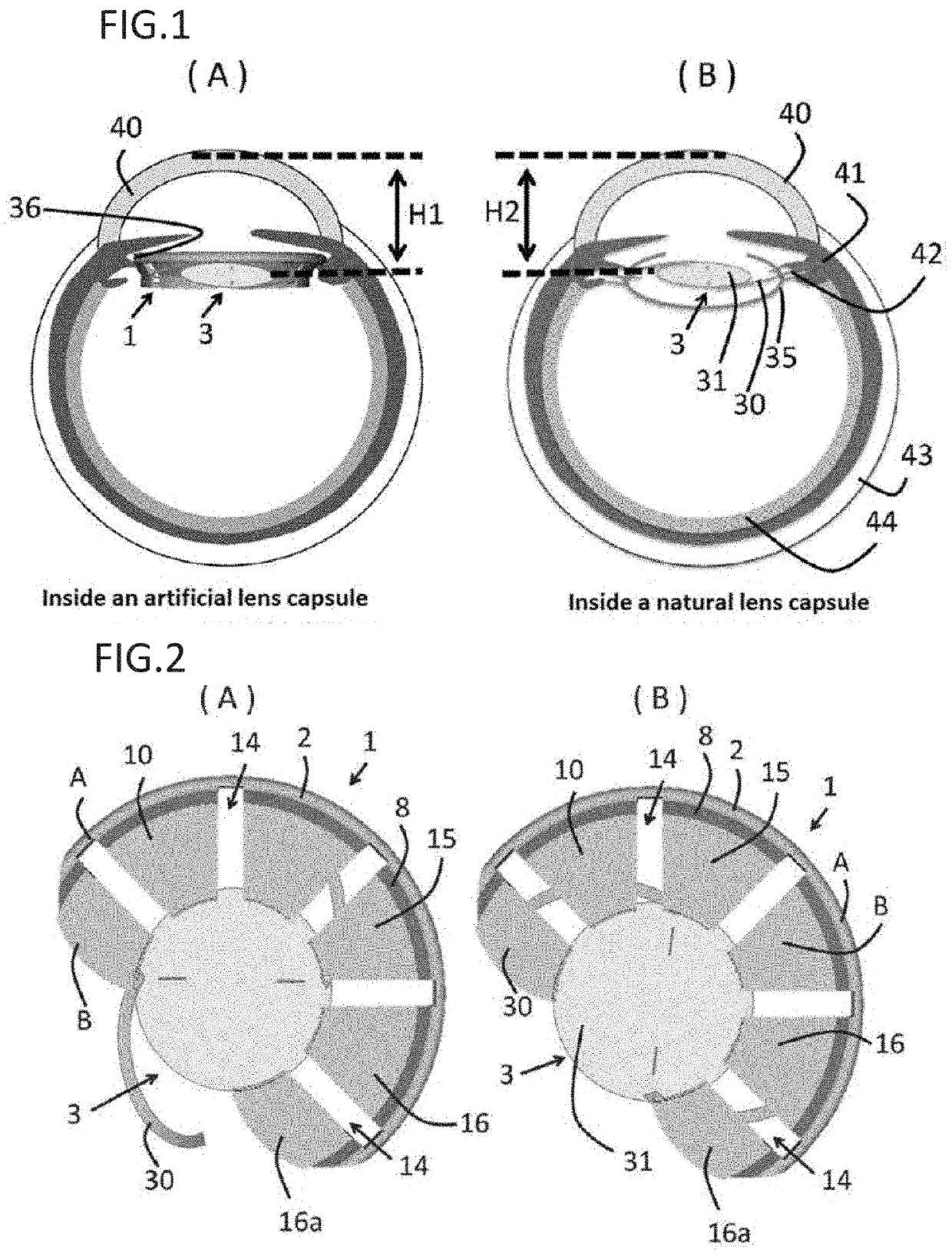
[0080]FIG. 1(A) is a cross-sectional view depicting the intraocular lens fixing device according to an embodiment of the invention when installed. FIG. 1(B) is a cross-sectional view schematically depicting an intraocular lens fixed to a natural lens capsule.

[0081]With conventional intracapsular fixation, the intraocular lens 3 is fixed within the lens capsule 35 so that the optical portion 31 of the intraocular lens 3 is positioned in a cavity inside the wound formed on the anterior capsule of the lens capsule 35, and the peripheral edge of the lens support 30 is positioned at the equator of the lens capsule 35 in place of a lens removed from the within the lens capsule 35 by surgery as depicted in FIG. 1B.

[0082]The intraocular lens fixing device 1 according to the present invention is inserted into an eye with a ruptured or lost lens capsule as depicted in FIG. 1A.

[0083]The intraocular lens fixing device 1 is formed with a material having elasticity and flexibility, so that a phys...

embodiment 2

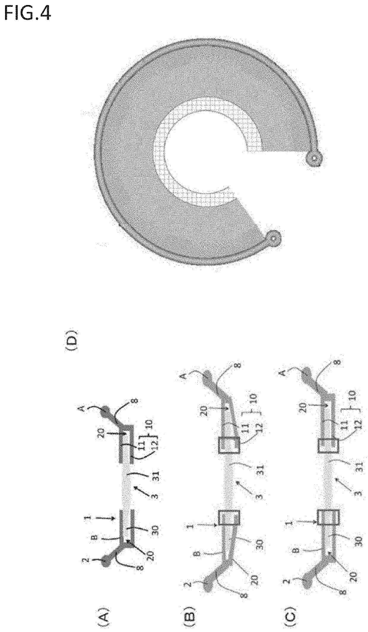
[0144]While embodiment 1 is a representative embodiment, other embodiments can also be used. As depicted in FIG. 7, the device 1 of embodiment 2 is substantially the same as embodiment 1, with the exception of changing the cross-sectional shape of frame 2 to a rectangular or trapezoidal shape and changing the number of slits 14 in embodiment 1.

[0145]In this embodiment, the frame 2 of the device support (A) is formed in a nearly C-shaped when viewed from the front. The cross-section of the frame 2 is formed in an approximately trapezoidal shape. The intraocular lens housing B coupled to the device support A has the first clamping piece 11 extended toward the center in the radial direction from the frame 2 and the second clamping piece 12 arranged in parallel to the first clamping piece 11 with a space interposed therebetween. The element 16 of the holding piece 10 is formed by the first clamping piece 11 and the second clamping piece 12. A plurality of the elements 16 of the holding ...

embodiment 3

[0148]Embodiment 3 is an embodiment without a slit, which is exemplified in FIG. 8. As depicted in FIG. 8, the device 1 of embodiment 3 is the same as embodiment 1, with the exception of forming operational portions 19 having a through hole on both ends of the frame 2 formed into a C-shape, and not forming the slit 14 on the extended portion 8 of the intraocular lens housing B and on the holding piece 10 extending inside from the inner end of the extended portion 8 in embodiment 1.

[0149]In other words, the frame 2 of the device support A is shaped in nearly a C-shape. The cross-section of the frame 2 is formed in a nearly circular shape. The intraocular lens housing B coupled to the device support A has the extended portion 8 extended toward the center in the radial direction from the frame 2 and the holding piece 10 extended toward the inside from the inner end of the extended portion 8. The holding piece 10 has the first and second clamping pieces 11 and 12 arranged in parallel wi...


PUM


Abstract

Provided is an intraocular lens affixing device which makes it possible to affix an intraocular lens of any kind with respect to the inside of an eye with a ruptured or deleted lens capsule. The intraocular lens affixing device is provided with a device support portion (A) and an intraocular lens housing portion (B) connected to the device support portion (A). The device support portion (A) includes a frame 2 having a shape matching a ciliary sulcus 36. Also provided is an affixing kit for inserting an intraocular lens, the kit being provided with a) an intraocular lens affixing device; and b) an injector for injecting the affixing device.

Description

TECHNICAL FIELD[0001]The present invention relates to an invention in the ophthalmic field. More specifically, the present invention relates to a fixing device for fixing an intraocular lens implanted into an eye, i.e., artificial lens capsule. In one aspect, the device of the invention can be used in place of a lens with an impaired function due to an ophthalmic disorder such as cataract or if the lens capsule itself has also been lost. The device of the invention can also be used in place of a lens supporting tissue (lens capsule or the zonule of Zinn) with an impaired function due to an ophthalmic disorder such as lens capsule rupture, lens dislocation, or intraocular lens dislocation.BACKGROUND ART[0002]Cataract surgeries insert an intraocular lens as a replacement for a clouded lens. Generally, an intraocular lens is fixed inside the original support of the lens, lens capsule (intracapsular fixation).[0003]An intraocular lens 3 comprising a lens support 30 depicted in FIG. 14 i...

Claims


Application Information

Patent Timeline
Patent Type & Authority Applications(United States)
IPC IPC(8): A61F2/16
CPCA61F2002/169A61F2/16A61F2002/16901A61F2002/16902A61F2230/0006A61F2220/0025A61F2230/0008A61F2002/169053A61F2/1662A61F2/1694A61F2/1648A61F2220/0008
Inventor KOJIMA, KENTARO
Owner KYOTO PREFECTURAL PUBLIC UNIV CORP
Why Eureka
Try Eureka