Optical inspection method, optical inspection device and optical inspection system

Active Publication Date: 2020-01-02
UTECHZONE CO LTD
View PDF0 Cites 11 Cited by
  • Summary
  • Abstract
  • Description
  • Claims
  • Application Information

AI Technical Summary

Benefits of technology

[0004]The disclosure provides an optical inspection method, an optical inspection device and an optical inspection system

Problems solved by technology

However, automatic defect inspecting technology still has high error rate, such that double check

Method used


Image

  • Optical inspection method, optical inspection device and optical inspection system
  • Optical inspection method, optical inspection device and optical inspection system
  • Optical inspection method, optical inspection device and optical inspection system

Examples


Embodiment Construction

[0022]Reference will now be made in detail to the present preferred embodiments of the disclosure, examples of which are illustrated in the accompanying drawings. Wherever possible, the same reference numbers are used in the drawings and the description to refer to the same or like parts. Furthermore, it is noted that the term “a” or “an” entity refers to one or more of that entity. As such, the terms “a” (or “an”), “one or more” and “at least one” can be used interchangeably herein.

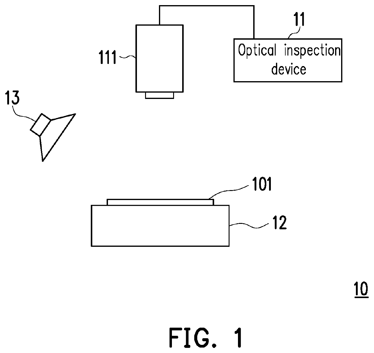
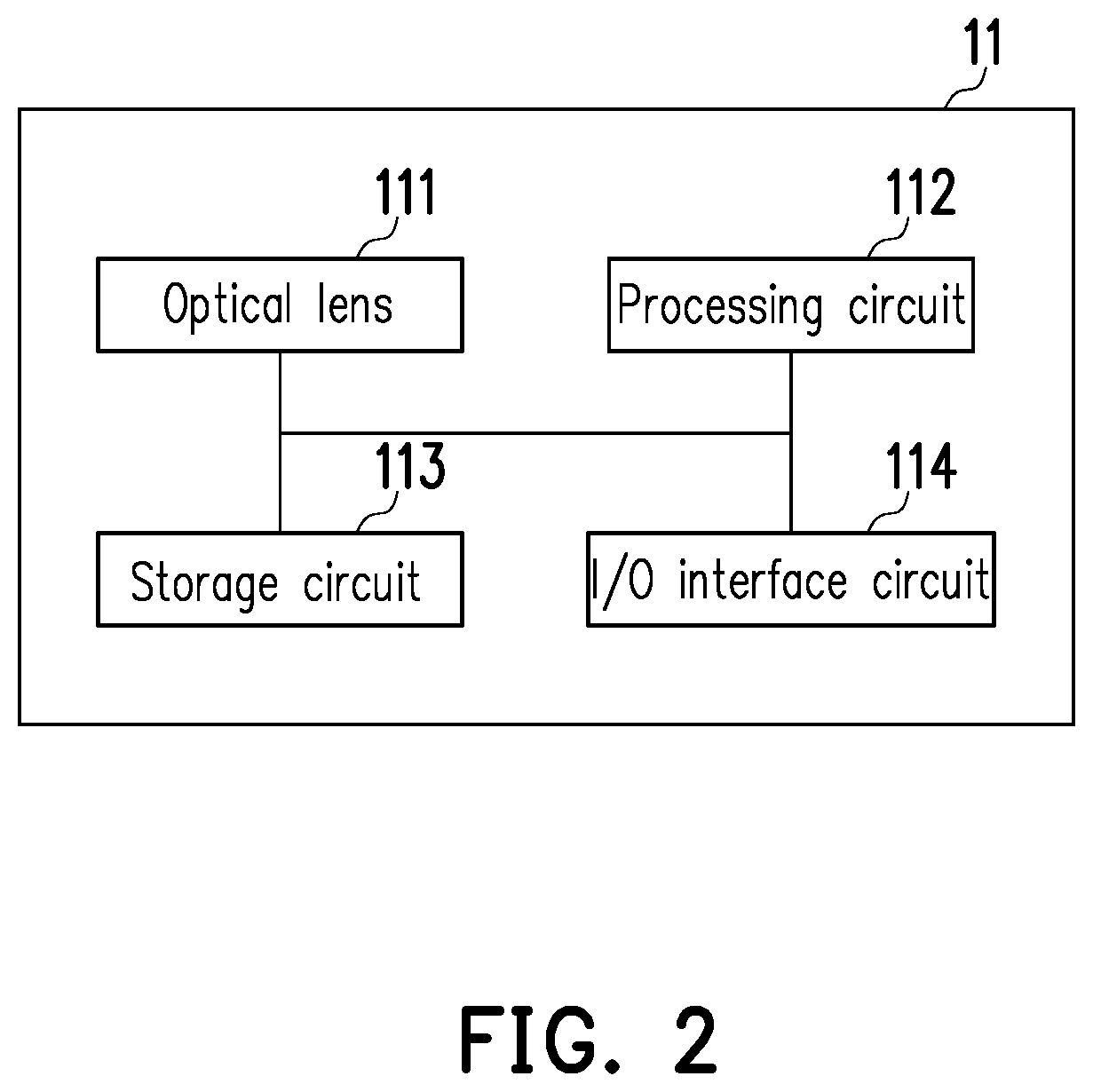
[0023]FIG. 1 is a schematic diagram of an optical inspection system according to an embodiment of the disclosure. FIG. 2 is a schematic diagram of an optical inspection device according to an embodiment of the disclosure. Referring to FIG. 1 and FIG. 2, an optical inspection system 10 may be applied to an automated optical inspection (AOI) equipment to perform a surface defect inspection on a workpiece, such as a semiconductor chip, a wafer, a panel, a circuit board (e.g., a printed circuit board (PCB), ...


PUM


Abstract

An optical inspection method for an optical inspection device comprising an optical lens is provided according to an embodiment of the disclosure. The optical inspection method includes: obtaining a first image of an object by the optical lens; performing an edge detection on the first image to obtain a second image comprising an edge pattern; and performing a defect inspection operation on the second image based on a neural network architecture to inspect a defect pattern in the second image. In addition, an optical inspection device and an optical inspection system are provided according to embodiments of the disclosure.

Description

CROSS-REFERENCE TO RELATED APPLICATION[0001]This application claims the priority benefit of Taiwan application serial no. 107122594, filed on Jun. 29, 2018. The entirety of the above-mentioned patent application is hereby incorporated by reference herein and made a part of this specification.BACKGROUNDTechnical Field[0002]The disclosure relates to a defect pattern inspection technology, particularly to an optical inspection method, an optical inspection device and an optical inspection system.Description of Related Art[0003]Before an electronic component is sent out from the factory, the electronic component is usually inspected with visual confirmation by a human employee, so as to determine whether a defect is existed in the electronic component. Based on some improved technologies, Artificial Intelligence (AI) is gradually designed to support an ability of automatically inspecting defects to reduce the work loading of the human employee. However, automatic defect inspecting techn...

Claims


Application Information

Patent Timeline
IPC IPC(8): G06K9/46G01N21/892G06T7/13G06V10/147G06V10/44G06V10/56G06V10/764G06V10/774
CPCG01N21/892G06T7/13G06K9/4604G06T2207/20084G01N21/8851G01N2021/8887G01N2021/8883G01N21/95607G01N2201/1296G06T7/0002G06T2207/10024G06V10/147G06V10/44G06V10/56G06V10/764G06V10/774G06F18/2413
Inventor AMBIKAPATHI, ARULMURUGANHSU, MING-TANGLU, CHIA-LIANGFANG, CHIH-HENG
Owner UTECHZONE CO LTD
Why Eureka
Try Eureka