Power conversion system and method for pre-charging dc-bus capacitors therein

a power conversion system and capacitor technology, applied in emergency power supply arrangements, process and machine control, instruments, etc., can solve the problems of high cost, large size, and new bottleneck in the pre-charging of dc-bus capacitors in combination-typed power converters, and achieve the effect of less power consumption and small siz

Active Publication Date: 2020-01-02
DELTA ELECTRONICS INC
View PDF4 Cites 20 Cited by
  • Summary
  • Abstract
  • Description
  • Claims
  • Application Information

AI Technical Summary

Benefits of technology

[0020]In view of the above, it is an aspect of the present invention to provide a power conversion system and a method for pre-charging DC-Bus capacitors therein to effectively pre-charge DC-Bus capacitors in various power modules and to allow the pre-charging circuit to be smaller in size and less in power consumption.
[0024]In summary, it is preferable in the present invention that each of the power modules can be independently pre-charged by separately disposing a pre-charging unit in each of the power modules and electrically connecting the pre-charging unit directly to the DC-Bus capacitor therein, and when the pre-charging unit in a single power module fails, the main power circuit of the entire system will not fail as a result. Moreover, since the main loop current does not flow through the pre-charging unit in each power module, a lower power loss can be achieved with the same duration of charging, and the pre-charging unit may be smaller in size.
[0026]Preferably, in the present invention, auxiliary power modules are used for independently assisting to power the respective pre-charging units in the power modules, that is, the medium voltage input current of the system is not directly used for charging, thereby achieving recharging at a breakout point, making it easier to control charging, and avoiding the risk of unbalance of capacitor voltage in the respective DC-Bus capacitors in the power modules.

Problems solved by technology

However, pre-charging of DC-Bus capacitors in the combination-typed power converter becomes a new bottleneck.
1) First, it is limited to the voltage levels of the main power circuits in the power modules 1 to N. The soft-start resistors RA, RB, and RC, and the switches SA, SB, and SC are required to be medium-voltage elements, which are large in size and lead to a high cost. For example, the size of a 10 kV SVG pre-charging circuit may be 600 mm*600 mm*600 mm in volume. Further, in control of those switches SA, SB and SC, the voltage level isolation at medium voltage has to be taken into consideration.
2) Second, since the pre-charging circuit is disposed in the main power circuit, the pre-charging circuit can only be fed with medium-voltage alternating current passively. The power modules 1 to N cannot be hot-plugged.
3) Third, since the soft-start resistors RA, RB, RC are connected in series to a main power circuit between respective power input ends of the power modules 1 to N and respective medium voltage inputs of the system, the entire system may not work when the soft-start resistors RA, RB, RC or the switches SA, SB, and SC fails.
4) Fourth, the pre-charging can only be done in one time. If an additional control is not provided, there may be a risk of unbalance in capacitor voltage.
5) Fifth, when grid voltage changes, the soft-start resistors RA, RB, RC and the switches SA, SB, SC have to be redesigned.
1) First, since the soft-start resistors and the switches in the pre-charging circuit are connected in series to the main power circuits of the power modules 1 to N, the current levels of those soft-start resistors and switches have to be selected depending on the current levels of the main power circuits of each power module. Therefore, those soft-start resistors and switches have a large volume. For example, the size of a single switch is not less than 50.5 mm*32.9 mm*36 mm in volume. Further, too many switches may increase the cost of the system.
2) Second, since the soft-start resistors and the switches in the pre-charging circuit are connected in series to the main power circuit of the power modules 1 to N, the entire system may not work when some soft-start resistor or some switch fails..
3) Third, since the pre-charging circuit is disposed in the main power circuit, the pre-charging circuit can only be fed with medium-voltage alternating current passively.
4) Fourth, the pre-charging can only be done in one time. If an additional control is not provided, there may be a risk of unbalance in capacitor voltage.

Method used


Image

  • Power conversion system and method for pre-charging dc-bus capacitors therein
  • Power conversion system and method for pre-charging dc-bus capacitors therein
  • Power conversion system and method for pre-charging dc-bus capacitors therein

Examples


Embodiment Construction

[0044]In order to make the description of the present invention more elaborate and complete, reference may be made to the accompanying drawings and the various examples described below. Like numbers in the drawings indicate like components. On the other hand, some known components and steps are not described in the embodiments to avoid unnecessarily limiting the present invention. In addition, some known structures and elements are shown in the drawings schematically to simplify the drawings.

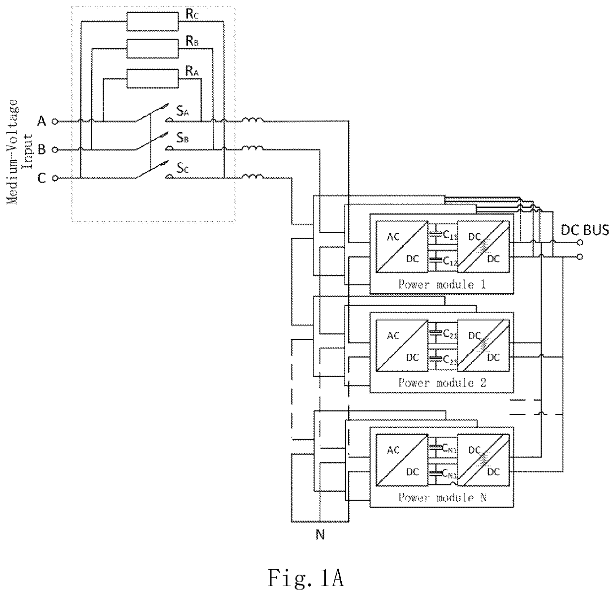
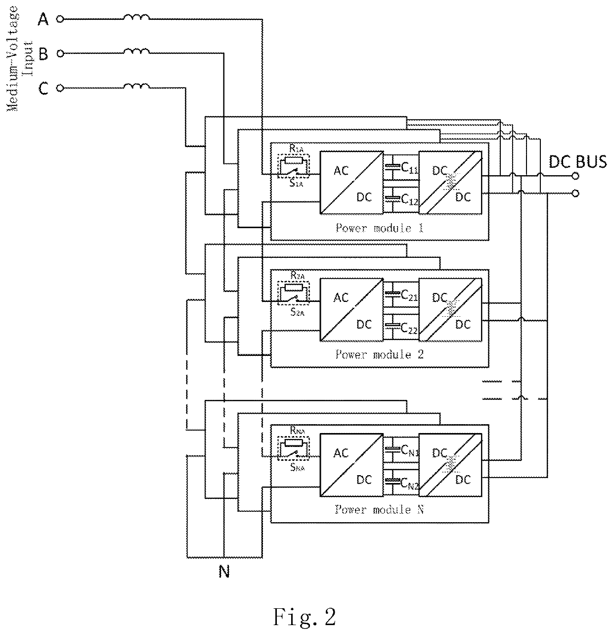
[0045]FIG. 3A is a schematic diagram showing a configuration of a power conversion system according to one embodiment of the present invention. As shown in FIG. 3A, the power conversion system according to the embodiment comprises a plurality of power modules 1 to N (N is a positive integer greater than or equal to 2). The power modules 1 to N are cascaded-connected at input side and connected in parallel at output side. Each of the power modules 1 to N includes a power input end, a charging inp...


PUM


Abstract

The present invention discloses a power conversion system and a method for pre-charging DC-Bus capacitors therein. The power conversion system comprises a plurality of power modules, each including a power input end; a charging input end; a power output end; at least one power conversion unit, each of the power conversion unit including at least one DC-Bus capacitor and being electrically connected to the power input end and the power output end; and a pre-charging unit electrically connected to the charging input end for receiving direct current and electrically connected to the DC-Bus capacitor for pre-charging the DC-Bus capacitor. The power input ends of the plurality of power modules are connected in series and then electrically connected to an AC power source, and the power output ends of the plurality of power modules are connected in parallel.

Description

CROSS-REFERENCE TO RELATED APPLICATIONS[0001]This non-provisional application claims priority under 35 U.S.C. § 119(a) on Patent Application No. 201810708851.X filed in P.R. China on Jul. 2, 2018, the entire contents of which are hereby incorporated by reference.[0002]Some references, if any, which may include patents, patent applications and various publications, may be cited and discussed in the description of this invention. The citation and / or discussion of such references, if any, is provided merely to clarify the description of the present invention and is not an admission that any such reference is “Prior Art” to the present invention described herein. All references listed, cited and / or discussed in this specification are incorporated herein by reference in their entireties and to the same extent as if each reference was individually incorporated by reference.BACKGROUND OF THE PRESENT INVENTION1. Field of the Present Invention[0003]The present invention relates to a power co...

Claims


Application Information

Patent Timeline
Patent Type & Authority Applications(United States)
IPC IPC(8): H02J7/00H02M7/162H02M3/158
CPCH02J2007/0059H02M7/219H02M7/1626H02J7/0052H02M2001/0074H02J9/061H02M7/217H02M1/36H02M7/125H02M3/3376H02M3/33561H02M7/06H02M7/487H02J1/102H02J7/345H02J2207/50H02J1/001Y02B70/10H02M1/0074H02M1/008H02M1/0058H02M1/007H02M7/4835H02M1/0095H02J7/00H02J2207/20H02M7/7575
Inventor CHEN, XINZHANG, WEIQIANGHAO, SHIQIANGLIU, HONGYAO
Owner DELTA ELECTRONICS INC
Why Eureka
Try Eureka