Method and machine for balancing a vehicle wheel

a vehicle wheel and balancing machine technology, applied in the direction of measuring devices, structural/machine measurement, instruments, etc., can solve the problems of not being able to perform the correction with difficult to fasten the balancing weight inside the rim, and difficult to achieve the exact necessary value, etc., to minimize the residual imbalance and minimize the imbalance

Active Publication Date: 2020-02-06
BUZZI CARLO
View PDF0 Cites 3 Cited by
  • Summary
  • Abstract
  • Description
  • Claims
  • Application Information

AI Technical Summary

Benefits of technology

[0024]determining the axial position of the correction plane where a static balancing weight is to be located so as to minimize the imbalance on the reference planes of the wheel, where the residual imbalance is to be measured;
[0025]selecting an optimum commercial balancing weight which, when positioned on the correction plane, minimizes the residual imbalance on the reference planes where the balancing tolerance is considered;

Problems solved by technology

Fastening the balancing weights inside the rim may be difficult because there is no certain reference that corresponds to the chosen correction plane used in the calculations by the machine.
Masses of lower value are rarely available.
This entails a possible balancing error, because it may not be possible to perform the correction with the exact necessary value.
Actually, it is well-known that static imbalance is the one that causes the greatest vibrations that are detectable for the driver.
This is a very clear error for the art but is normally not considered in practice in using wheel balancing machines.
This apparent detail entails the possibility of poor balancing and unwanted vibrations on the vehicle when the two residues substantially in step, although per se within tolerance, generate an important static residue that however is not considered by the operator.
This is useful for balancing narrow wheels, for example motorcycle or car and truck wheels with low performance.
However, the position along the axis of the wheel where the correction mass is to be placed is never indicated or prescribed, and therefore it is customary to place it in any axial position.
The axial position of the mass, however, conditions the extent of the dynamic residual imbalance.

Method used


Image

  • Method and machine for balancing a vehicle wheel
  • Method and machine for balancing a vehicle wheel
  • Method and machine for balancing a vehicle wheel

Examples


Embodiment Construction

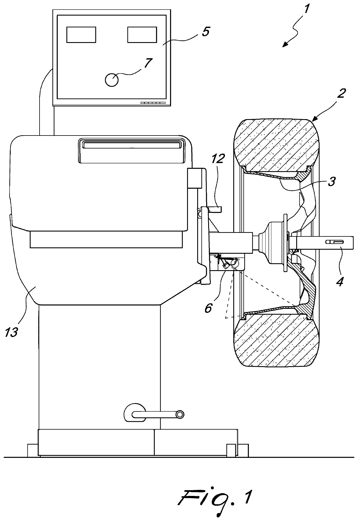
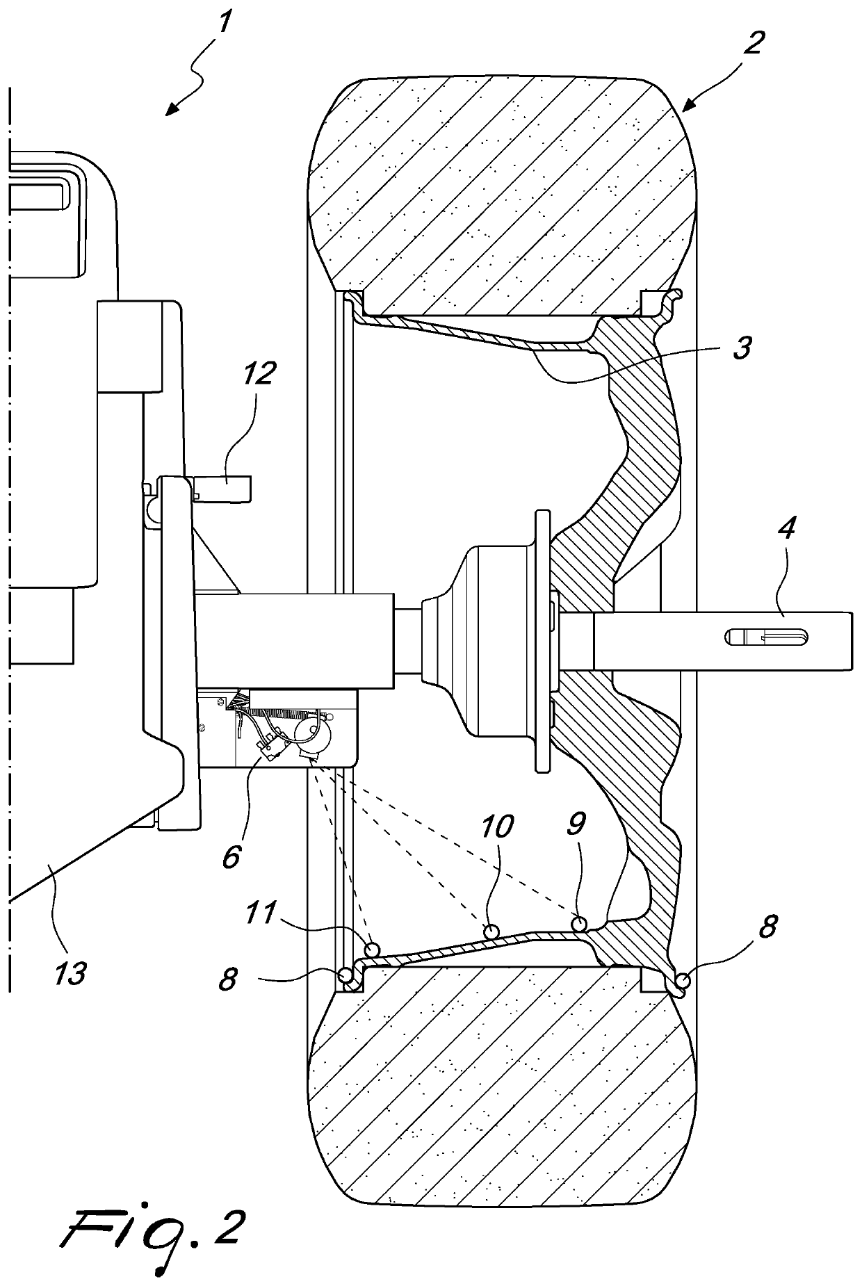
[0032]With reference to the cited figures, the balancing machine according to the invention, designated generally by the reference numeral 1, includes a load-bearing structure 13 provided with a rotating shaft 4 which is extended outside the structure and is adapted to support and rotate a wheel to be balanced 2.

[0033]The machine 1 includes sensors for measuring vibrations and a computerized system for data processing and control.

[0034]The machine 1 also includes a system for measuring the positions of the planes and of the possible radii of correction, referred to the load-bearing structure 13, i.e., to the measurement transducers.

[0035]This allows the control system to transfer the imbalance values, read as signals equal to the forces measured by the sensors, to the corresponding correction planes.

[0036]The position measurement system can be, for example, a device with manual calibration, caliber, designated by the reference numeral 12, of the type described in EP1653210, or a dev...


PUM


Abstract

A method for balancing a vehicle wheel includes mounting a wheel to be balanced on a rotating shaft of a machine computerized for measuring imbalances, and selecting an optimum commercial balancing weight which, when positioned on a correction plane, minimizes residual imbalance on reference planes of the wheel where the balancing tolerance is considered. One compares the residual imbalance value at the reference planes with the prescribed balancing tolerance after subtracting a vector of the static imbalance generated by the optimum balancing weight. An indicator device is activated to indicate on the wheel the optimum axial position of a correction plane for a balancing weight where the residual imbalance at the reference planes is within tolerance.

Description

CROSS-REFERENCE TO RELATED APPLICATION[0001]The present application is a continuation-in-part of application Ser. No. 15 / 427,727 filed Feb. 8, 2017.BACKGROUND OF THE INVENTION[0002]The present invention relates to a method and to a machine for balancing a vehicle wheel.[0003]As is known, the wheels of vehicles require frequent balancing operations, for example at each tire change or following abnormal wear of the tire.[0004]The balancing operation consists in fitting small balancing weights, made of heavy material, on the wheel so as to compensate the imperfect distribution of the mass of the wheel with respect to its rotation axis, which by definition is the cause of the imbalance.[0005]A rotating body is in fact defined as balanced when the geometric condition in which the rotation axis coincides with the centroid and main inertia axis is met.[0006]Measurement of the imbalance is obtained by means of a balancing machine where the wheel is turned, after being fixed to a precision f...

Claims


Application Information

Patent Timeline
Patent Type & Authority Applications(United States)
IPC IPC(8): G01M1/08G01M1/28G01M1/32
CPCG01M1/326G01M1/08G01M1/28
Inventor BUZZI, CARLO
Owner BUZZI CARLO
Why Eureka
Try Eureka