Electronic device
- Summary
- Abstract
- Description
- Claims
- Application Information
AI Technical Summary
Benefits of technology
Problems solved by technology
Method used
Image

Examples
first embodiment
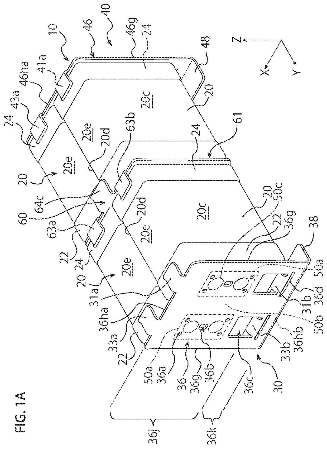
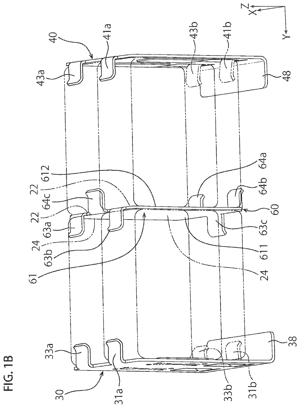
[0034]FIG. 1A is a schematic perspective view illustrating a capacitor 10 as an electronic device according to First Embodiment of the present invention. The capacitor 10 has capacitor chips 20 as chip components, a pair of outer metal terminals 30 and 40, and an intermediate metal terminal 60. The capacitor 10 according to First Embodiment has four capacitor chips 20, but the capacitor 10 may have any plural capacitor chips 20.
[0035]Incidentally, each embodiment is described with a capacitor where the capacitor chips 20 are equipped with the outer metal terminals 30 and 40 and the intermediate metal terminal 60, but the ceramic electronic device of the present invention is not limited to this capacitor and may be a chip component other than capacitors equipped with the outer metal terminals 30 and 40 and the intermediate metal terminal 60.
[0036]In the figures, the X-axis, the Y-axis, and the Z-axis are perpendicular to each other. The X-axis is parallel to a direction where the cap...
second embodiment
[0153]FIG. 7A is a schematic perspective view of a capacitor 10a according to a variation of the capacitor 10 shown in FIG. 1A. In the outer metal terminal 30 of the capacitor 10a shown in FIG. 7A, a base of the upper arm portion 31a (a boundary between the arm portion 31a and the terminal body 36) among the pair of arm portions 31a and 31b (the same applies to the arm portions 33a and 33b / the same applies hereinafter) is narrower than the lower arm portion 31b.
[0154]In this structure, the pair of arm portions 31a and 31b stably holds the capacitor chip 20, and the capacitor chip 20 and the outer metal terminal 30 can securely and firmly be connected. Other structure of the present embodiment is similar to First Embodiment and demonstrates similar effects to First Embodiment.
[0155]In the capacitor 10a shown in FIG. 7A, the upper arm portion 31a (33a) is narrower than the lower arm portion 31b (33b) in the X-axis direction, but the upper arm portion 31a (33a) may be wider than the l...
third embodiment
[0156]FIG. 7B is a schematic perspective view of a capacitor 10b according to a variation of the capacitor 10 shown in FIG. 1A. In the outer metal terminal 30 of the capacitor 10b shown in FIG. 7B, reinforcement pieces 36f are formed on the terminal body 36 in a lower position of the non-joint region 50b failing to overlap with the joint regions 50a in the Z-axis direction (the pair of engagement arm portions 31a and 31b faces each other (the same applies to 33a and 33b / no mention hereinafter)). The pair of reinforcement pieces 36f is bent inward from both sides of the terminal body 36 in the X-axis direction toward the capacitor chips 20 (Y-axis direction). The pair of reinforcement pieces 36f is formed on the terminal body 36 so as to face each other in the X-axis direction.
[0157]Each of the reinforcement pieces 36f has a length Z1 in the Z-axis direction determined to include at least the non-joint region 50b from the lower edge of the joint region 50a to the lower arm portion 31...
PUM
 Abstract
Description
Claims
Application Information
 - R&D Engineer
- R&D Manager
- IP Professional
- Industry Leading Data Capabilities
- Powerful AI technology
- Patent DNA Extraction
Browse by: Latest US Patents, China's latest patents, Technical Efficacy Thesaurus, Application Domain, Technology Topic.
© 2024 PatSnap. All rights reserved.Legal|Privacy policy|Modern Slavery Act Transparency Statement|Sitemap