Adaptable airport system with industrial zones and clean energy generation

a technology of industrial zones and airports, applied in the field of adaptable airports, can solve the problems of pollution, huge noise generation of departing and arriving aircraft, and high cost of airport benefits

Inactive Publication Date: 2020-02-13
BICKELMEYER MICHAEL
View PDF8 Cites 0 Cited by
  • Summary
  • Abstract
  • Description
  • Claims
  • Application Information

AI Technical Summary

Benefits of technology

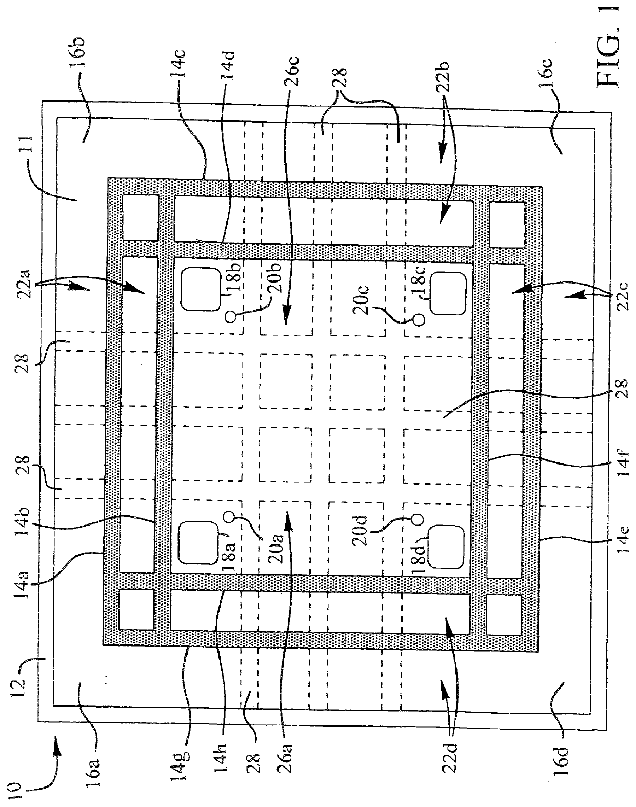
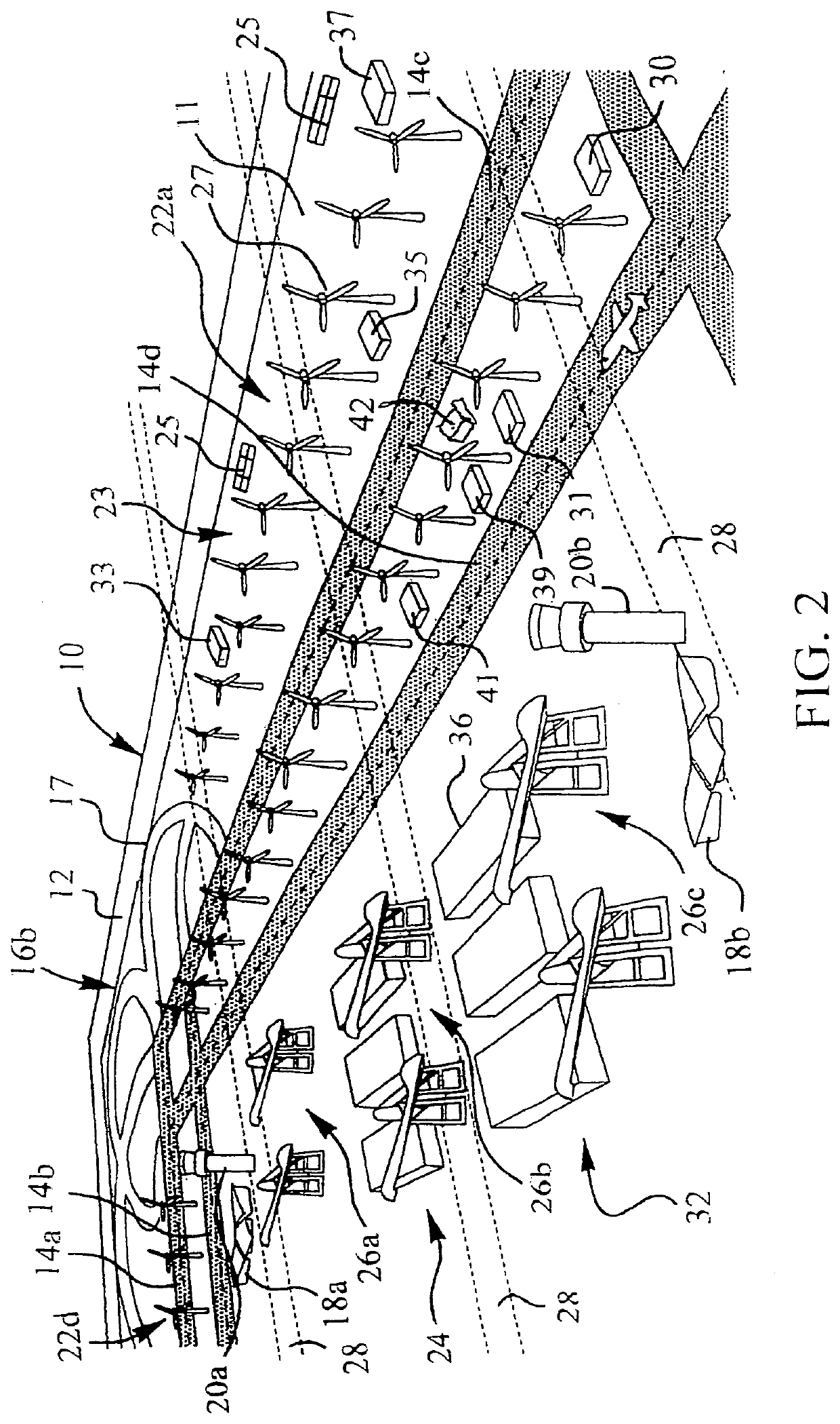
[0004]According to an embodiment of the present invention, an environmentally-friendly airport with renewable energy sources. The environmentally-friendly airport includes a security zone encompassing the land area of the airport, and a plurality of runways across the land area. There are one or more terminals within the security zone encompassing the land area of the airport. Further, a plurality of power generator systems are disposed within the land area for generating renewable, clean energy, and an industrial zone is placed within a boundary by the runways.
[0005]According to another embodiment of the present invention, a method of operating an environmentally-friendly airport with renewable energy sources. The method includes encompassing the land area of the airport with a security zone and running a plurality of runways across the land area. The method further includes constructing one or more terminals within the security zone encompassing the land area of the airport. The method further includes generating renewable, clean energy using a plurality of power generator systems within the land area. Finally, the method includes providing an industrial zone on the land area of the airport bounded by the runways.

Problems solved by technology

On the other hand, these benefits come at a considerable cost.
One of the greatest drawbacks associated with airports is pollution.
Departing and arriving aircraft generate huge levels of noise, which presents a major disturbance to people living in proximity to the airport.
These aircraft also emit large quantities of pollutant gases.
Moreover, the construction of a massive airport often strips the surrounding area of natural features to counterbalance such pollution.

Method used


Image

  • Adaptable airport system with industrial zones and clean energy generation
  • Adaptable airport system with industrial zones and clean energy generation

Examples


Embodiment Construction

[0010]In the description that follows, numerous details are set forth in order to provide a thorough understanding of the present invention. It will be appreciated by those skilled in the art that variations of these specific details are possible while still achieving the results of the present invention. Well-known processing steps are generally not described in detail in order to avoid unnecessarily obfuscating the description of the present invention.

[0011]In the description that, follows, exemplary dimensions may be presented for an illustrative embodiment of the invention. The dimensions should not be interpreted as limiting. They are included to provide a sense of proportion. Generally speaking, it is the relationship between various elements, where they are located, their contrasting compositions, and sometimes their relative sizes that is of significance.

[0012]In the drawings accompanying the description that follows, often both reference numerals and legends (labels, text d...


PUM

PropertyMeasurementUnit
areaaaaaaaaaaa
land areaaaaaaaaaaa
structureaaaaaaaaaa

Abstract

An environmentally-friendly airport with renewable energy sources. The environmentally-friendly airport includes a security zone encompassing the land area of the airport, and a plurality of runways across the land area. There are one or more terminals within the security zone encompassing the land area of the airport. Further, a plurality of power generator systems are disposed within the land area for generating renewable, clean energy, and an industrial zone is placed within a boundary formed by the runways.

Description

TECHNICAL FIELD OF THE INVENTION[0001]The present invention relates generally to an environmentally-friendly airport with renewable energy sources. More specifically, the present invention relates to an airport complete with plurality of runways with one or more terminals, preferably within a security zone and a plurality of power generator systems disposed within the airport for generating renewable, clean energy.BACKGROUND OF THE INVENTION[0002]Airports, particularly large international airports, have long been centers of both commerce and pollution. On one hand, they offer one of the most significant means to transport goods and people. A high capacity airport can represent a boon to an emerging local economy or can act as the backbone of a more established region. The airport itself can provide immense employment benefits and it can also boost the presence of other sectors, like tourism, industry, education, and military, among many others.[0003]On the other hand, these benefits...

Claims


Application Information

Patent Timeline
Patent Type & Authority Applications(United States)
IPC IPC(8): B64F1/36H02S10/12H01M8/10C25B1/02F03D9/25G21B1/21
CPCB64F1/36F03D9/255H01M2008/1293H01M2250/10H01M8/10G21B1/21C25B1/02H02S10/12F03D9/43Y02B90/10Y02E10/50Y02E10/72Y02E30/10Y02E60/50Y02P20/133Y02P80/20
Inventor BICKELMEYER, MICHAEL
Owner BICKELMEYER MICHAEL
Why Eureka
Try Eureka