
Method and apparatus for measuring the flow rate of a shielding gas mixture

Active Publication Date: 2020-02-13
KEMPPI OY
View PDF0 Cites 0 Cited by
  • Summary
  • Abstract
  • Description
  • Claims
  • Application Information

AI Technical Summary

Benefits of technology

The patent describes a way to monitor and adjust the flow of shielding gas during welding using a mobile measurement system that can be integrated into the shielding gas distribution system. This allows for continuous monitoring and adjustment of the gas flow, which can improve the quality and efficiency of welding processes.

Problems solved by technology

However, intermittent measurements are often inconvenient and yield much less information than a continuous measurement would.
Document U.S. Pat. No. 6,450,024 discloses an apparatus for determining the mass flow rate of a fluid using thermal means, but it does not disclose a sensor which could be conveniently integrated to a welding apparatus.

Method used


Image

  • Method and apparatus for measuring the flow rate of a shielding gas mixture
  • Method and apparatus for measuring the flow rate of a shielding gas mixture
  • Method and apparatus for measuring the flow rate of a shielding gas mixture

Examples


Embodiment Construction

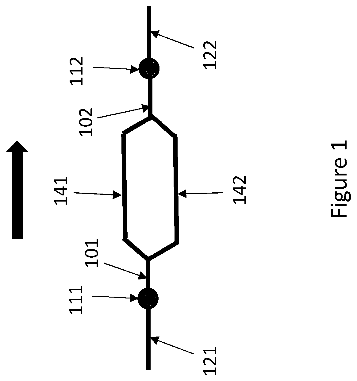
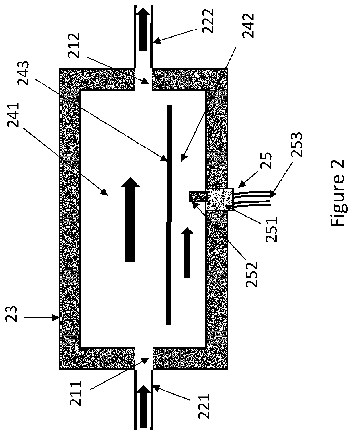
[0021]This disclosure describes a sensor apparatus for measuring the flow rate of a shielding gas in a welding apparatus, comprising at least one inlet and at least one outlet, wherein the at least one inlet is in fluid connection with one or more bypass channels and with one or more sensor channels for leading fluid into the sensor apparatus. The at least one outlet is in fluid connection with the same bypass channels and sensor channels as the at least one inlet for leading fluid out of the sensor apparatus. At least one input hose is connected to the at least one inlet and configured to transfer the shielding gas to the sensor apparatus. At least one output hose is connected to the at least one outlet and configured to transfer the shielding gas out of the sensor apparatus and towards the weld.

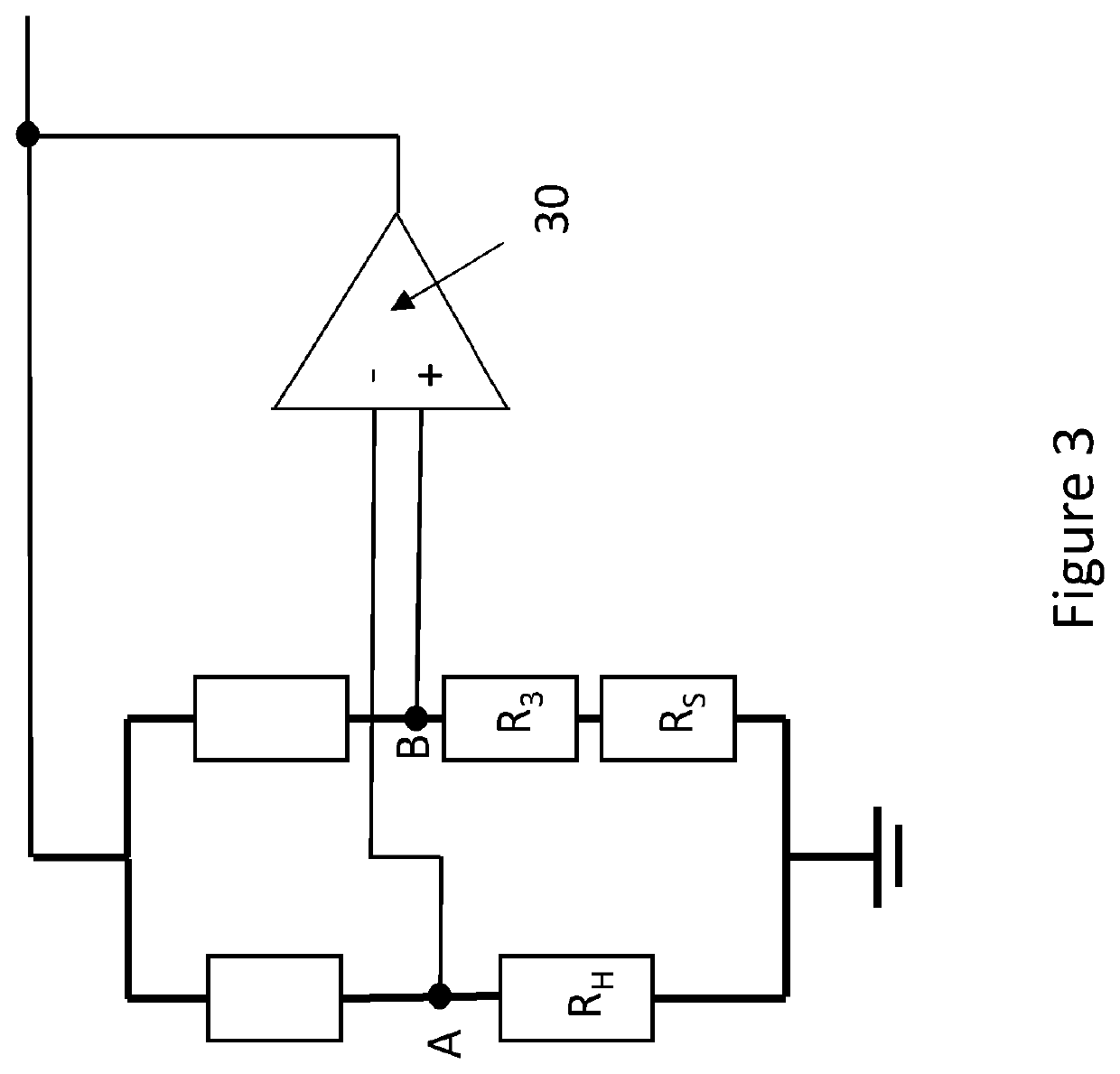
[0022]The apparatus also comprises one or more thermal mass flow sensors connected to the one or more sensor channels, and a control unit configured to retrieve sensor responses from the on...


PUM

PropertyMeasurementUnit
Temperatureaaaaaaaaaa
Flow rateaaaaaaaaaa

Abstract

The disclosure relates to a sensor apparatus and a method for measuring the flow rate of a shielding gas in a welding apparatus. The sensor apparatus comprises at least one inlet and at least one outlet in fluid connection with one or more bypass channels and with one or more sensor channels, and at least one input hose and one output hose. The apparatus also comprises one or more thermal mass flow sensors connected to the one or more sensor channels, and a control unit configured to retrieve sensor responses from the one or more thermal mass flow sensors and to determine the flow rate of the shielding gas through the sensor apparatus based on the retrieved sensor response and calibration data, wherein the calibration data comprises one or more characteristic curves comprising gas flow values and sensor response values. The control unit is configured to retrieve from a memory unit: the composition of the shielding gas; the number of active thermodynamic degrees of freedom which the molecules of each gas component in the shielding gas possess at the retrieved shielding gas temperature; a characteristic curve for each gas component separately, which consists of sensor response data as a function of gas flow rate, measured in a calibration experiment conducted with a pure gas consisting only of that gas component. The control unit is configured to calculate a new, mixture-specific characteristic curve for the gas mixture as a weighted average of the pure-gas characteristic curves, wherein the weight assigned to each value on a pure-gas characteristic curve is a product of the concentration percentage of that gas component in the shielding gas mixture and the number of active thermodynamic degrees of freedom which the molecules of that gas component possess at the retrieved shielding gas temperature; and to use the mixture-specific characteristic curve as the characteristic curve for the shielding gas mixture by retrieving from this characteristic curve the calibration gas flow rate which corresponds most closely to the retrieved new sensor response; and to identify this flow rate as the current flow rate of the shielding gas through the sensor apparatus. The sensor apparatus also comprises a display unit configured to display the determined flow rate of the shielding gas to a user and / or a memory unit for storing the determined flow rate of the shielding gas.

Description

FIELD OF THE DISCLOSURE[0001]The present disclosure relates to shielding gases used in gas metal arc welding, and more particularly to methods for measuring the flow rate of shielding gases with thermal mass flow sensors.BACKGROUND OF THE DISCLOSURE[0002]In gas metal arc welding, an electric arc burns between an electrode and a workpiece. The electrode extends outward from a tubular gas nozzle, and a shielding gas which surrounds the electrode also flows through the nozzle towards the work piece during welding. The shielding gas prevents impurities from coming into contact with the melted weld and controls heat input. The shielding gas also stabilizes the weld by preventing splatter. The shielding gas may be inert, or it may be a reactive gas which may interact chemically with the weld, for example by reducing or increasing oxidation.[0003]Shielding gases typically comprise argon, helium, oxygen, hydrogen, nitrogen and carbon dioxide, either as a pure gas which comprises only one of...

Claims


Application Information

Patent Timeline
IPC IPC(8): G01F1/696G01F1/684G01F15/04G01F25/00G01F15/12B23K9/095B23K9/16
CPCG01F15/043G01F25/0053G01F1/6965G01F1/6842B23K9/0956B23K9/16G01F15/125G01F1/684G01F15/046B23K9/32G01F25/15B23K9/0953B23K9/164
Inventor TERHO, TUOMAS
Owner KEMPPI OY
Learn More