An ultrasound system with a tissue type analyzer

a tissue type analyzer and ultrasound technology, applied in the field of ultrasound systems, can solve problems such as the difference between the attenuation slopes of received echo signals

Active Publication Date: 2020-02-13
KONINKLJIJKE PHILIPS NV
View PDF7 Cites 10 Cited by
  • Summary
  • Abstract
  • Description
  • Claims
  • Application Information

AI Technical Summary

Benefits of technology

[0022]Acoustic wave attenuation increases with increasing frequency. Therefore, it may be beneficial producing the wide view of the volumetric region with larger penetration depth but reduced spatial resolution and the detailed field view within the wide field of view, wherein the ROI can be imaged with higher spatial resolution. The advantage of the present invention that both fields of view can be produced using the same CMUT transducer array during a single ultrasound scan.
[0023]In another embodiment, the ultrasound system further comprises an image display coupled to the image processor, which displays both the wide view of the volumetric region and the detail view of the region of interest. Both fields of view may be displayed to a user either next to each other as separate ultrasound images or in a spatial registration as one ultrasound image.
[0024]In yet another embodiment the ultrasound system further comprises a user interface coupled to the ROI identifier and responsive to a manual selection of the ROI within the volumetric region.
[0025]This gives the user an opportunity to manually select the ROI to be identified by the ROI identifier. Optionally, the user interface can be also coupled to the frequency control, such that the user can also select the relatively low and high frequencies of the beams steered within the volumetric region and within the region of interest correspondingly.
[0026]In a further embodiment the array is a two-dimensional array or one-dimensional array.
[0027]Depending on the array's design the ultrasound system may be providing the three dimensional ultrasound images or two dimensional ultrasound images (2D slices) of the volumetric region.

Problems solved by technology

This results in a distinct difference between the attenuation slopes of the received echo signals, when they travel through the blood pool and another soft tissue.

Method used


Image

  • An ultrasound system with a tissue type analyzer
  • An ultrasound system with a tissue type analyzer
  • An ultrasound system with a tissue type analyzer

Examples


Embodiment Construction

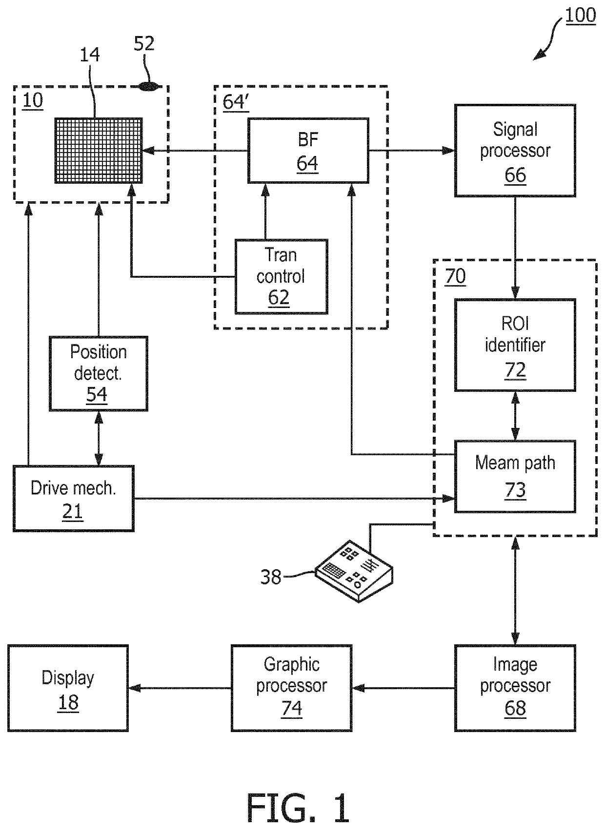
[0039]FIG. 1 shows schematically and exemplarily an ultrasound system 100 for variable frequency imaging of a volumetric region in accordance with the principles of the present invention. A probe 10 comprises an array 14 of capacitive micromachined ultrasound transducers (CMUTs) suitable for operation in a collapsed mode. This array 14 can be either two dimensional or one dimensional array. The probe can be of any ultrasound probe type: a regular ultrasound diagnostic probe, an interventional ultrasound probe or a low profile ultrasound probe (patch) suitable to be attached to a patient for a longer period of time.

[0040]The CMUTs of the array transmit ultrasound beams over a volumetric field of view 131 (FIG. 5) (comprising the volumetric region) and receive echoes in response to the transmitted beams. The transducers of the array 14 transducer are coupled to a beamformer 64, which controls a steering of the ultrasound beams transmitted by the CMUTs of the array transducer 14. The b...


PUM


Abstract

An ultrasound system (100) for imaging a volumetric region comprising a region of interest (12) comprising: a probe having an array of CMUT transducers (14) adapted to transmit ultrasound beams and receive returning echo signals over the volumetric region; a beamformer (64) coupled to the array and adapted to control ultrasound beam transmission and provide ultrasound image data of the volumetric region; a transducer controller (62) coupled to the beamformer and adapted to vary driving pulse characteristics of the CMUT transducers, a region of interest identifier (72) enabling an identification of a region of interest on the basis of the ultrasound image data; a beam path analyzer (70) responsive to the ROI identification and arranged to detect an attenuating tissue type in between the probe and the ROI based on a depth variation in attenuation of the received signal; wherein the transducer controller is further adapted to change, based on the attenuating tissue type detection, at least one parameter of the driving pulse characteristics.

Description

FIELD OF THE INVENTION[0001]The invention relates to an ultrasound system for imaging a volumetric region comprising a region of interest comprising: an array of CMUT transducers adapted to transmit ultrasound beams and receive returning echo signals over the volumetric region; a beamformer coupled to the array and adapted to control ultrasound beam transmission and provide ultrasound image data of the volumetric region; a transducer controller coupled to the beamformer and adapted to vary driving pulse characteristics of the CMUT transducers; and a region of interest (ROI) identifier enabling an identification of a region of interest on the basis of the ultrasound image data, and which identifier is adapted to generate identification data indicating the region of interest within the volumetric region.[0002]The present invention further relates to a method of variable frequency ultrasound imaging of a volumetric region using such an ultrasound system.BACKGROUND OF THE INVENTION[0003...

Claims


Application Information

Patent Timeline
Patent Type & Authority Applications(United States)
IPC IPC(8): G01S7/52A61B8/00B06B1/02B06B1/20G01S15/89
CPCG01S7/52036A61B8/585G01S7/5202B06B1/0292G01S7/5208B06B1/20G01S15/8925G01S15/8952A61B8/54G01S7/5205G01S15/8922G01S7/52074
Inventor PEKAR, MARTINDITTMER, WENDY UYEN
Owner KONINKLJIJKE PHILIPS NV
Why Eureka
Try Eureka