Power generation system technical field

a power generation system and power generation technology, applied in the direction of electric generator control, machines/engines, mechanical equipment, etc., can solve the problems of large voltage drop at the terminal, large ripple on the grid, power drop at the output terminal, etc., to increase the voltage available to the exciter, reduce the cost and space requirements, and reduce the effect of cos

Active Publication Date: 2020-02-13
ABB (SCHWEIZ) AG
View PDF0 Cites 2 Cited by
  • Summary
  • Abstract
  • Description
  • Claims
  • Application Information

AI Technical Summary

Benefits of technology

[0009]A key point of the invention is therefore that the power generation system is able to increase the voltage available to the exciter by, for example, switching the DC sides in series thereby doubling the voltage, without requiring a second source of electrical power such as batteries or capacitors. In other words, the power generation system allows for dynamically reconfiguring the topology of an excitation system comprising the first rectifier, the second rectifier, the exciter and the selector device online during a voltage drop at terminals of the generator, i.e. during a so-called low voltage ride through, LVRT. Thus, the power generation system can increase the excitation system voltage capabilities during severe voltage dips in the grid due to varies types of faults, thereby ensuring that the excitation system complies with grid code requirements.
[0010]During normal operation conditions the DC sides as outputs of the first rectifier and the second rectifier can be connected in parallel. During LVRT conditions the selector device may connect the outputs of the first rectifier and a second rectifier in series thereby increasing a total output voltage available for the field winding via the exciter. Having at least two rectifiers, i.e. the first rectifier and the second rectifier allows for a redundant operation and resulting in significantly reduced cost and space required, when comparing to prior art solutions requiring a second source of electrical power. The proposed solution has the further advantage that existing installations can be easily upgraded as the additional hardware required for the second rectifier and the exciter only requires low volume.
[0011]In sum, the power generation system is characterized by a great flexibility in designing a step-up transformer and the rectifiers for continuous operation, for example in case of redundant operation, or for short-time operation, for example in case only a voltage increase during LVRT is desired. The proposed excitation system can be applied for direct excitation systems as well as for indirect excitation systems, with or without an external source. For example, an extra cabinet may be attached to an existing excitation system that provides an extra voltage boost by switching the DC sides of the rectifiers in parallel during faults, while being on standby during normal operation conditions. Besides that the proposed solution is very attractive for retrofit scenarios, while it also allows reducing cases in which an existing excitation system is over-sized in order to handle longer periods of ride through conditions.
[0023]In an alternative embodiment in this regard the selector device comprises a first breaker and a second breaker, and the second line of the first rectifier is connected via the first breaker with the second line of the second rectifier to the exciter and the first line of the second rectifier is connected via the second breaker with the first line of the first rectifier to the exciter. Preferably, the first breaker and / or the second breaker are arranged in parallel to the first diode and / or the second diode for bypassing the respective diode. Providing a breaker has the advantage of reducing conduction losses during normal operation.
[0024]According to a further preferred embodiment the switch is provided as an electric switch, a mechanical switch, a mechanical breaker, and / or a semiconductor switch, for example comprising an IGBT, thereby allowing an easy and cost-effective implementation.
[0029]Further embodiments and advantages of the method will be derived by the person skilled in the art in analogy to the power generation system as described above. The method allows for advantageously increasing the voltage available to the exciter without requiring a second source of electrical power such as batteries or capacitors. The first rectifier and the second rectifier can be advantageously used for redundant operation and voltage increase during a low voltage ride through, thereby significantly reducing the cost and space requirements compared to prior art methods.

Problems solved by technology

However, the grid may experience a variety of single or multiple line-to-line or line-to-ground faults that result in a large drop of the voltage at the terminals.
When this drop occurs at the terminals of the generator, it effects the voltage at an input of the step-down transformer and results in a power drop at output terminals of the exciter that feeds the field winding of the synchronous generator.
If such fault lasts for a relatively long period the generator may fall out of synchrony and the power plant comprising the generator is shutdown resulting in large-scale ripple on the grid and large financial losses.

Method used


Image

  • Power generation system technical field
  • Power generation system technical field
  • Power generation system technical field

Examples


Embodiment Construction

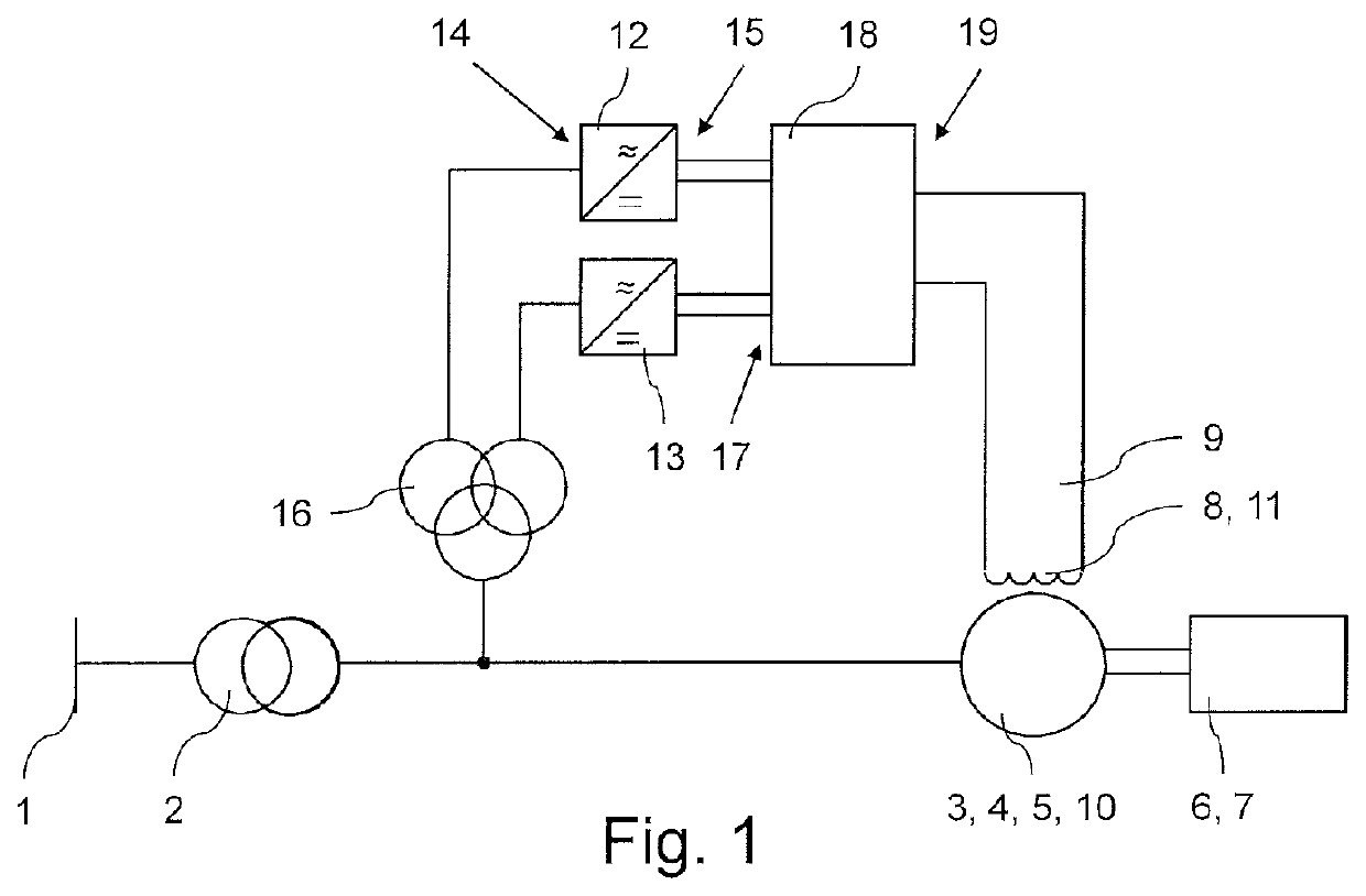
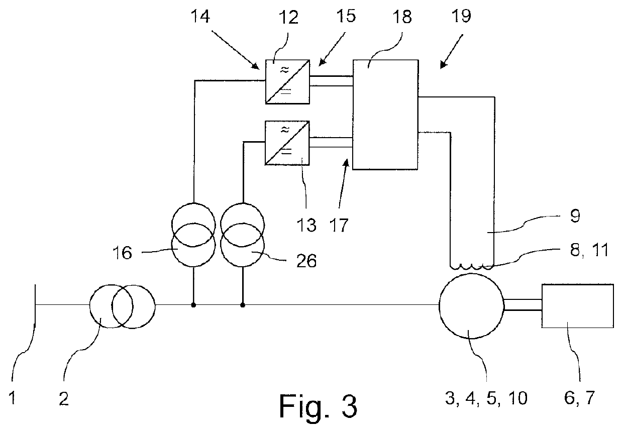
[0037]FIG. 1, FIGS. 3 and 4 each show a power generation system according to preferred embodiments of the invention in schematic views. An AC power grid 1 is connected via a step-up power transformer 2 to a synchronous generator 3. The generator 3 comprises a rotor 4, a stator 5 and a primary mover 6, which rotates the rotor 4. The step-down transformer 2 is connected to the stator 4. A governor 7 is provided for controlling mechanical power of the primary mover 6. The generator 3 further comprises a field winding 8, which can be fed with DC power by an exciter 9 for exciting the generator 3. Alternatively or in addition the generator 3 comprises a main machine 10 and the exciter 9 comprises a field wound or brushless rotor 11 for exciting the main machine 10.

[0038]A first rectifier 12 and a second rectifier 13 are provided each having an AC side 14 and DC side 15. The AC side 14 of the first rectifier 12 and of the second rectifier 13 are connected via a first step-down transformer...


PUM


Abstract

The invention relates to a power generation system, comprising a synchronous generator (3) for converting mechanical power into electrical power at an output side configured for connecting an AC power grid (1), a first rectifier (12) and a second rectifier (13) each having an AC side (14) connected to the output side of the generator (3) and a DC side (15), an exciter (9) configured for exciting the, and a selector device (18) having an input side (17) and an output side (19), the input side (17) connected to the DC side (15) of the first rectifier (12) and to the DC side (15) of the second rectifier (13) and the output side (19) connected to the exciter (9), whereby the selector device (18) is configured for switching the DC sides (15) in series or in parallel or for transmitting DC power from the first rectifier (12) and the second rectifier (13) corresponding to an arbitrary split ratio to the output side (19).

Description

[0001]The invention relates to a power generation system comprising a synchronous generator for converting mechanical power into electrical power and comprising a field winding, a step-up transformer connected to the generator and configured for connecting an AC power grid such that the step-up transformer is connected in series between the generator and the grid, and an exciter configured for exciting the generator by feeding the field winding DC power.BACKGROUND ART[0002]Synchronous generators are a major source of commercial electrical energy and are commonly used to convert mechanical power output of steam turbines, gas turbines, reciprocating engines or hydro turbines into electrical power feeding a grid. Synchronous generators usually comprise a rotor arranged in a centre of the generator containing a magnet, whereby a stator is electrically connected to a load such as the grid. The magnet generates a magnetic field which leads the rotor and thus the magnetic field to rotate w...

Claims


Application Information

Patent Timeline
Patent Type & Authority Applications(United States)
IPC IPC(8): H02P9/14H02J3/46H02J1/10H02J3/38F01D15/10H02P9/00
CPCH02J3/381H02P9/007F05D2220/7642H02J3/46H02J1/102H02P9/14F01D15/10
Inventor BAECHLE, MATTHIASWIESER, RUDOLFAL-HOKAYEM, PETERROHR, EDUARDO
Owner ABB (SCHWEIZ) AG
Why Eureka
Try Eureka