Temperature measuring device and method for measuring temperature

a temperature measurement and temperature technology, applied in the direction of heat measurement, thermometers with a/d converters, instruments, etc., can solve the problems of inability to correct mismatches and difficulty in decreasing size, and achieve the effect of suppressing mismatches and decreasing siz

Active Publication Date: 2020-02-27
SOCIONEXT INC
View PDF0 Cites 1 Cited by
  • Summary
  • Abstract
  • Description
  • Claims
  • Application Information

AI Technical Summary

Benefits of technology

[0007]In order to maintain accuracies of the temperature measurement, each of the first and second transistors in the art known to the inventors needs to have a element size to an extent such that effects of mismatch are suppressed. This leads to difficulties in decreasing size.

Problems solved by technology

However, in the art known to the inventors, as described above, such a mismatch cannot be corrected, between the first transistor provided with the current source unit and the first transistor provided with the sensor unit, as well as between the second transistor provided with the current source unit and the second transistor provided with the sensor unit.
This leads to difficulties in decreasing size.

Method used


Image

  • Temperature measuring device and method for measuring temperature
  • Temperature measuring device and method for measuring temperature
  • Temperature measuring device and method for measuring temperature

Examples


first embodiment

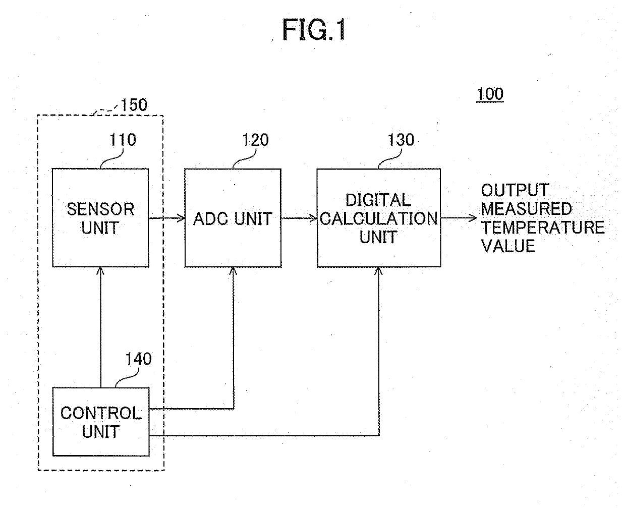
[0019]Explanation will be hereinafter provided for a first embodiment with reference to the drawings. FIG. 1 is a diagram for explaining a temperature measuring device according to the first embodiment.

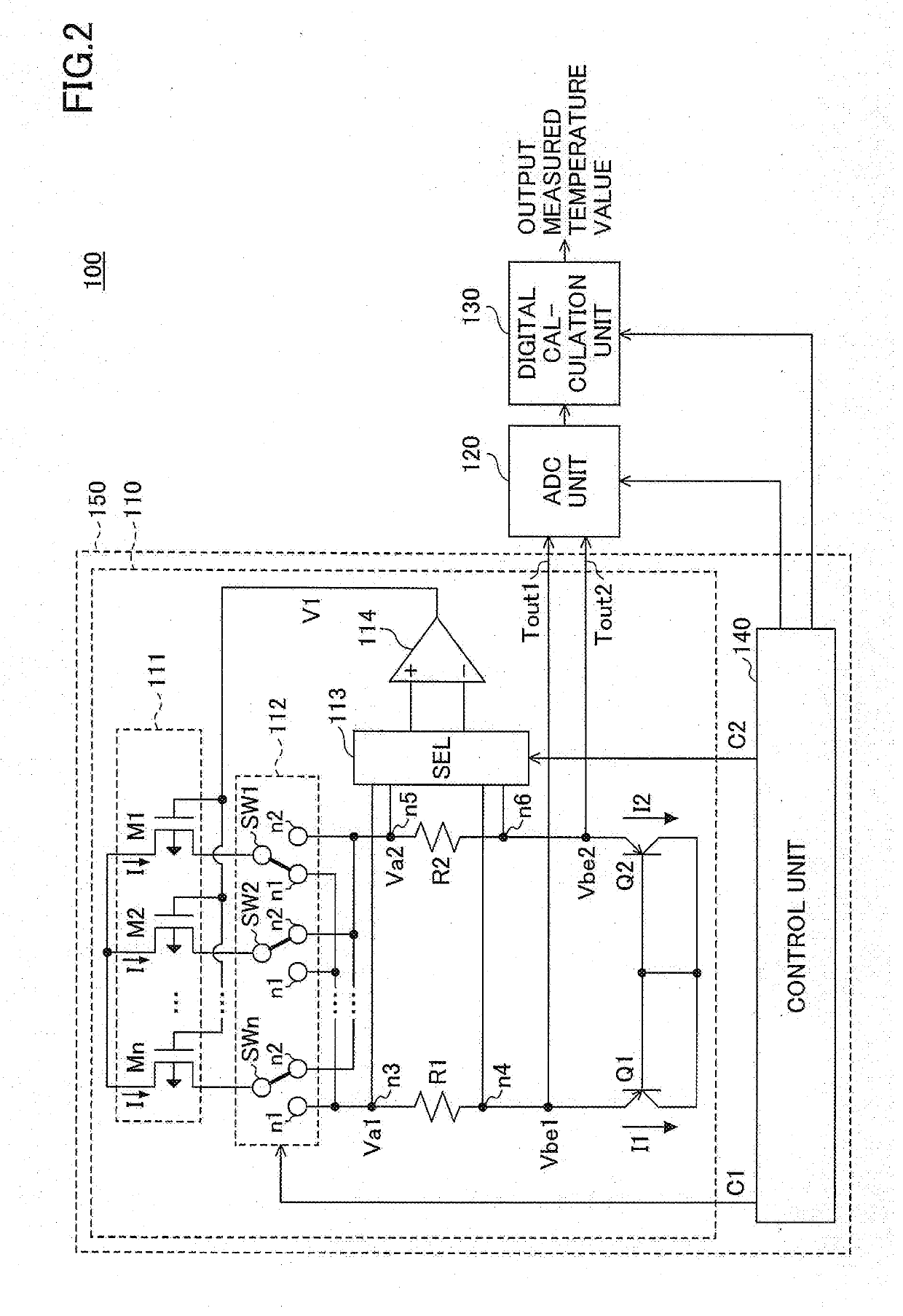
[0020]A temperature measuring device 100 in the present embodiment includes a sensor unit 110, an ADC (Analog to Digital Converter) unit 120, a digital calculation unit 130, and a control unit 140.

[0021]The sensor unit 110 includes a current source from which a current used as a reference to temperature measurement flows, and converts a temperature into a voltage value. In the present embodiment, with the current source being included in the sensor unit 110, downsizing of the temperature measuring device 100 is achieved. The sensor unit 110 will be described in detail below.

[0022]The ADC unit 120 converts a voltage outputted by the sensor unit 110 to a digital value, by A / D (Analog to Digital) conversion. The digital calculation unit 130 calculates a measured temperature value T by a ...

second embodiment

[0100]Hereafter, a second embodiment is described with reference to the drawings. In the second embodiment, a sensor unit does not include a selector 113, which is different from the first embodiment. Accordingly, in the following description in the second embodiment, only differences from the first embodiment will be described. For a similar functional configuration to the first embodiment, the same symbols as those used in the description of the first embodiment will be given; accordingly, explanation will be omitted.

[0101]FIG. 9 is a diagram for explaining a configuration of a temperature measuring device according to a second embodiment. The temperature measuring device 100A in the present embodiment includes a sensor unit 110A, an ADC unit 120, a digital calculation unit 130, and a control unit 140A.

[0102]Note that in an example of FIG. 9, the temperature measuring device 100A includes the ADC unit 120 and the digital calculation unit 130, but is not limited thereto. The ADC un...


PUM

PropertyMeasurementUnit
temperatureaaaaaaaaaa
forward voltageaaaaaaaaaa
voltageaaaaaaaaaa

Abstract

A temperature measuring device includes first and second semiconductor elements each of which has a p-n junction, a transistor group including a plurality of transistors of which respective sources are connected to a power source and of which respective gates are connected to each other, the plurality of transistors constituting a current source, the transistor group being configured to output a first current and a second current having a different magnitude from the first current to the first and second semiconductor elements, respectively, and a selector configured to select at least one first transistor and a plurality of second transistors different from the first transistor, from among the plurality of transistors.

Description

CROSS-REFERENCE TO RELATED APPLICATION[0001]This application is a continuation application of International Application No. PCT / JP2017 / 018169 filed on May 15, 2017, and designated the U.S., the entire contents of which are incorporated herein by reference.BACKGROUND OF THE INVENTION1. Field of the Invention[0002]The present disclosure relates to a temperature measuring device and a method for measuring temperature.2. Description of the Related Art[0003]Temperature measuring devices that improve accuracy of temperature measurement with suppressing increases in area have been proposed.[0004]As an example, such a temperature measuring device includes a current source unit that produces a current used as a reference to temperature measurement, a sensor unit that produces a voltage proportional to an absolute temperature based on a current value, and an ADC unit that executes the process of A / D conversion of the voltage. With respect to such a temperature measuring device, in order to me...

Claims


Application Information

Patent Timeline
Patent Type & Authority Applications(United States)
IPC IPC(8): G01K7/01G01K3/00
CPCG01K7/01G01K3/005G01K2219/00
Inventor HAMANO, HIROYUKIMIYAZAKI, TAKASHI
Owner SOCIONEXT INC
Why Eureka
Try Eureka