
A self-calibrating charge pump circuit based on current compensation

A current compensation and self-calibration technology, which is applied in the automatic control of power and electrical components, can solve problems such as changes in loop stability and difficulty in ensuring charge pump current matching, and achieve the effect of reducing the mismatch effect

Active Publication Date: 2022-02-15
NO 54 INST OF CHINA ELECTRONICS SCI & TECH GRP +1
View PDF0 Cites 0 Cited by
  • Summary
  • Abstract
  • Description
  • Claims
  • Application Information

AI Technical Summary

Problems solved by technology

However, when the frequency of phase detection is high and the range of current unit changes is large, the stability of the loop will change greatly. Therefore, it is difficult to ensure the matching of the charge pump current.

Method used


Image

  • A self-calibrating charge pump circuit based on current compensation
  • A self-calibrating charge pump circuit based on current compensation
  • A self-calibrating charge pump circuit based on current compensation

Examples


Embodiment Construction

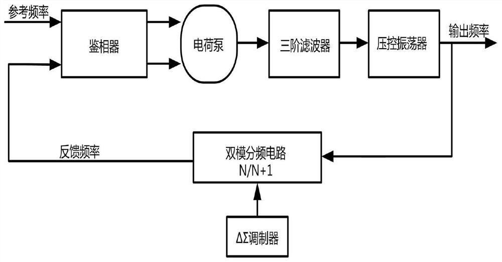
[0025] In order to make the purpose of the present invention, technical solutions and application superiority clearer, the following in conjunction with the appended Figure 1-5 The specific implementation manner of the present invention will be described in further detail.

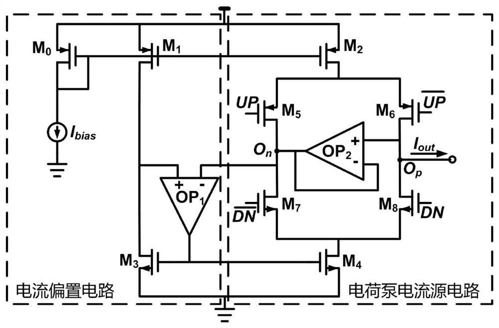
[0026] figure 1 is a general structural diagram of a frequency synthesizer, through figure 1 The modules shown work. First, the phase detector compares the input reference frequency with the feedback frequency. The charge pump converts the output phase difference of the phase detector into a voltage signal and outputs it to the filter for filtering, and finally sends it to the voltage-controlled oscillator. , the output frequency is fed back to the frequency and phase detector through the dual-mode frequency division circuit and the ΔΣ modulator, which completes the function of the frequency synthesizer; figure 2 Schematic diagram of the general structure of a conventional self-calibrating charge pump,...


PUM


Abstract

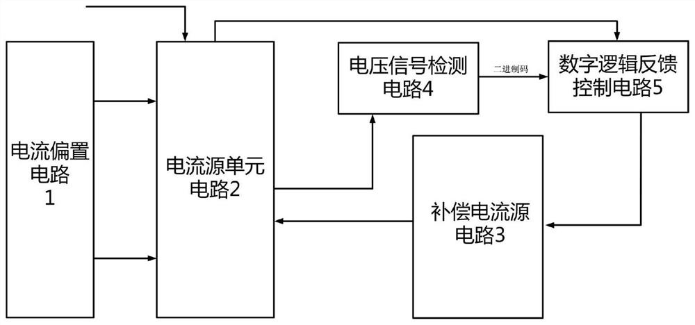
The invention discloses a self-calibrating charge pump circuit based on current compensation, belongs to a microcircuit structure in the field of integrated circuits, and relates to a charge pump circuit used in a frequency synthesizer to realize low current mismatch. The invention improves the traditional self-calibration charge pump, and adds a compensation current source circuit, a voltage signal detection circuit and a digital logic feedback control circuit on this basis. The voltage signal detection circuit detects the voltage of the output node of the charge pump and converts it into several digital codes to output to the digital logic feedback control circuit. The digital logic feedback control circuit outputs according to the obtained information and the current configuration of the charge pump current. Several digital codes control the compensation current source circuit to further reduce the mismatch effect of the charge pump output current. The invention can make the self-calibration charge pump have better stray and noise performance, has great significance for improving the quality of the output signal of the high-frequency broadband frequency synthesizer, and can save the investment in research and development.

Description

technical field [0001] The invention belongs to a microcircuit structure in the field of integrated circuits, and relates to a charge pump circuit used in a frequency synthesizer to realize low current mismatch. Background technique [0002] With the continuous development of radio frequency communication systems, the frequency bands of received and transmitted signals are getting wider and wider, and the requirements for signal quality are getting higher and higher, and the local oscillator circuit is a component of radio frequency transceiver circuit equipment, which plays a role The phase noise and spurious indicators of the local oscillator circuit will seriously affect the signal quality of the transceiver circuit. For the receiver, it will affect Intermodulation distortion, adjacent channel selectivity and channel blocking performance; for the transmitter, it will affect the modulation accuracy of the transmitter. Especially in the application environment that require...

Claims


Application Information

Patent Timeline
Patent Type & Authority Patents(China)
IPC IPC(8): H03L7/089
CPCH03L7/0895
Inventor 曲明杨格亮廖春连陈明辉石立志翟越范鹏飞王健王楠
Owner NO 54 INST OF CHINA ELECTRONICS SCI & TECH GRP
Learn More