Rotor core and manufacturing method for rotor core

a manufacturing method and technology of rotor core, applied in the direction of magnetic circuit rotating parts, lighting and heating apparatus, shape/form/construction of magnetic circuits, etc., can solve the problems of demagnetization, high temperature of magnets, and inability to dissipate heat generated in magnets to an outside, so as to improve the heat dissipation performance of magnets, increase the quantity of heat dissipated from the magnet surface to the outside, and good heat dissi

Active Publication Date: 2020-02-27
TOYOTA JIDOSHA KK
View PDF0 Cites 2 Cited by
  • Summary
  • Abstract
  • Description
  • Claims
  • Application Information

AI Technical Summary

Benefits of technology

[0011]With the foregoing configuration, the longitudinal direction of the filler with good thermal conductivity is oriented in a direction towards the surface of the magnet, and a quantity of heat dissipated from the magnet surface to the outside is increased. Thus, it is possible to provide a rotor core with good heat dissipation performance of the magnet to the outside.
[0012]The disclosure is able to improve dissipation performance of the magnet incorporated in the rotor core.

Problems solved by technology

However, when the magnet is fixed to the magnet slot by using resin like the related art described in JP 9-163649 A, because thermal conductivity of the resin is low, heat generated in the magnet cannot be dissipated to an outside sufficiently, temperature of the magnet becomes high and demagnetization occurs.
Thus, performance of the motor may be degraded.

Method used


Image

  • Rotor core and manufacturing method for rotor core
  • Rotor core and manufacturing method for rotor core
  • Rotor core and manufacturing method for rotor core

Examples


Embodiment Construction

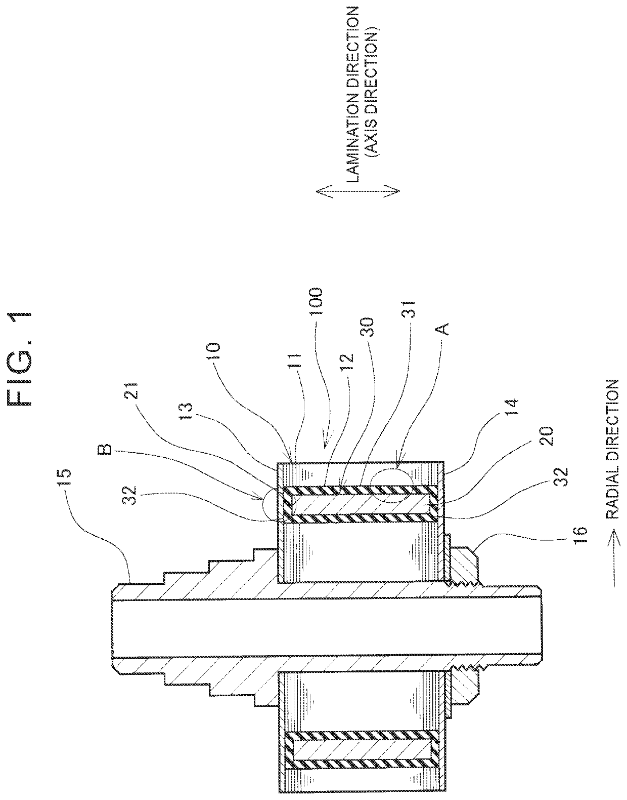
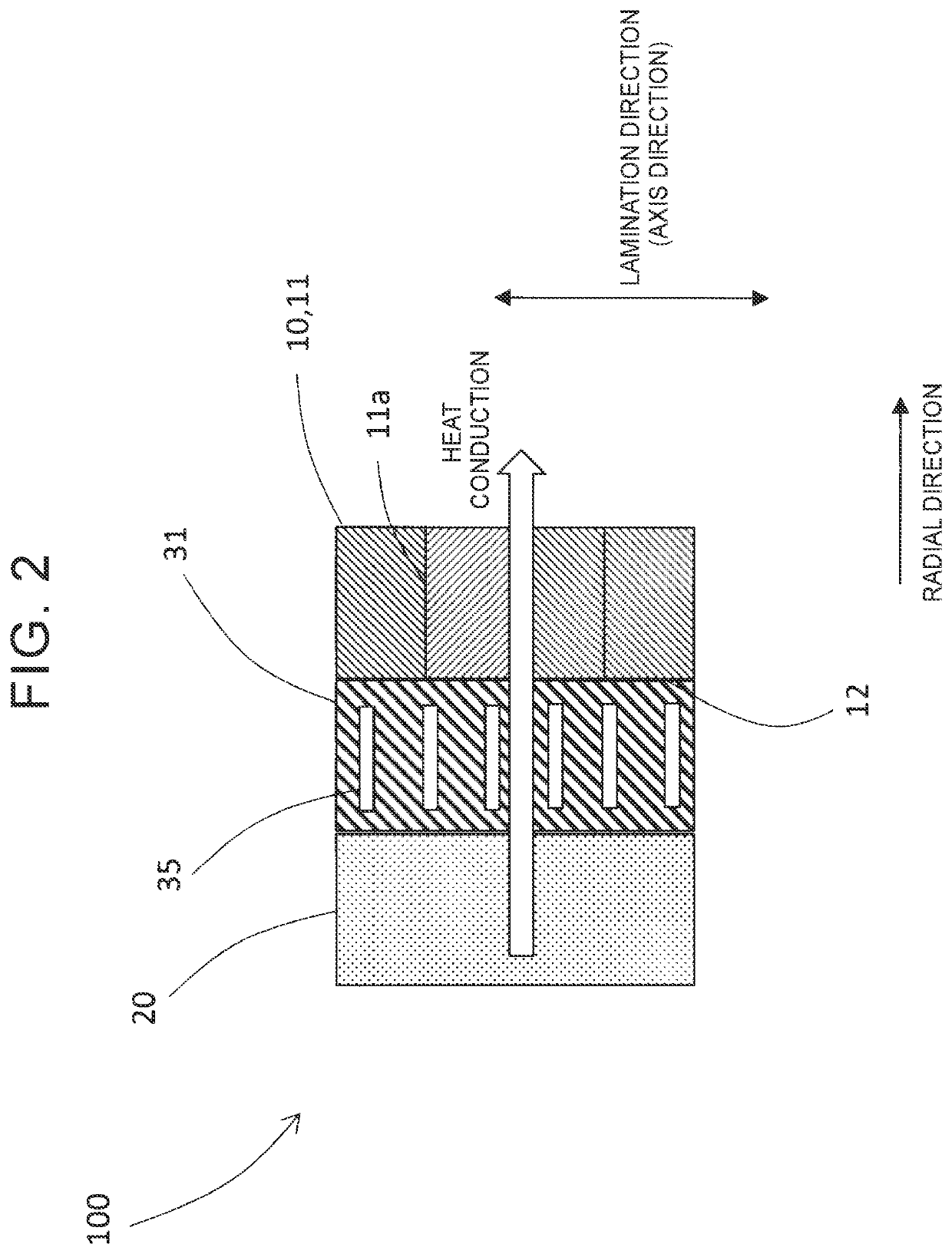
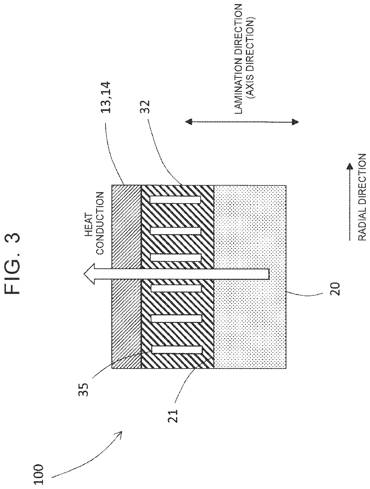
[0020]Hereinafter, a rotor core 100 according to an embodiment is described with reference to the drawings. The rotor core 100 includes a laminated iron core 10 in which electrical steel sheets 11 are laminated, and a magnet 20 that is fixed to an inside of a magnet slot 12 through resin 30. The magnet slot 12 is provided in the laminated iron core 10 and extends in an axis direction. As shown in FIG. 1, end plates 13, 14 sandwich the rotor core 100 from both end surfaces of the rotor core 100 in a lamination direction, and a shaft 15 is fitted into a center of the rotor core 100, and the rotor core 100 is fixed to the shaft 15 by a nut 16.

[0021]As shown in FIG. 1, the resin 31 is molded between an inner wall surface of the magnet slot 12 and an outside surface of the magnet 20, and resin 32 is molded between axial end surfaces 21 of the magnet 20, and the end plates 13, 14, respectively. The resin 31, 32 may be made of, for example, epoxy, phenol, and polyimide, but is not limited ...


PUM

PropertyMeasurementUnit
lengthaaaaaaaaaa
shapeaaaaaaaaaa
structureaaaaaaaaaa

Abstract

A rotor core includes a laminated iron core in which an electrical steel sheets are laminated, a magnet slot being provided in the laminated iron core and extending in a lamination direction of the laminated iron core, and a magnet that is fixed to an inside of the magnet slot through resin. The resin includes a filler, and the filler has a length in a longitudinal direction larger than a length in a width direction. The filler is oriented such that the longitudinal direction is directed towards a surface of the magnet.

Description

INCORPORATION BY REFERENCE[0001]The disclosure of Japanese Patent Application No. 2018-156320 filed on Aug. 23, 2018 including the specification, drawings and abstract is incorporated herein by reference in its entirety.BACKGROUND1. Technical Field[0002]The disclosure relates to a structure of a rotor core into which a magnet is incorporated, and to a manufacturing method for the rotor core.2. Description of Related Art[0003]There is a motor in which a rotor core is used. In the rotor core, an adhesion sheet made of thermosetting resin is placed between an inner surface of a magnet slot provided in a laminated iron core and a magnet, and the adhesion sheet is heated and cured so that the magnet is fixed to an inside of the magnet slot (for example, see Japanese Unexamined Patent Application Publication No. 9-163649 (JP 9-163649 A)).SUMMARY[0004]When a large current flows and a rotor is rotated at a high speed, a large induced current flows in a magnet incorporated in a rotor core, a...

Claims


Application Information

Patent Timeline
Patent Type & Authority Applications(United States)
IPC IPC(8): H02K9/22H02K1/27H02K1/28H02K15/03H02K15/12F28F21/00
CPCH02K15/12F28F21/00H02K15/03H02K9/22H02K1/28H02K1/276H02K9/223
Inventor KINPARA, HIROSHI
Owner TOYOTA JIDOSHA KK
Why Eureka
Try Eureka