Rfic module, RFID tag, and article
- Summary
- Abstract
- Description
- Claims
- Application Information
AI Technical Summary
Benefits of technology
Problems solved by technology
Method used
Image
Examples
first exemplary embodiment
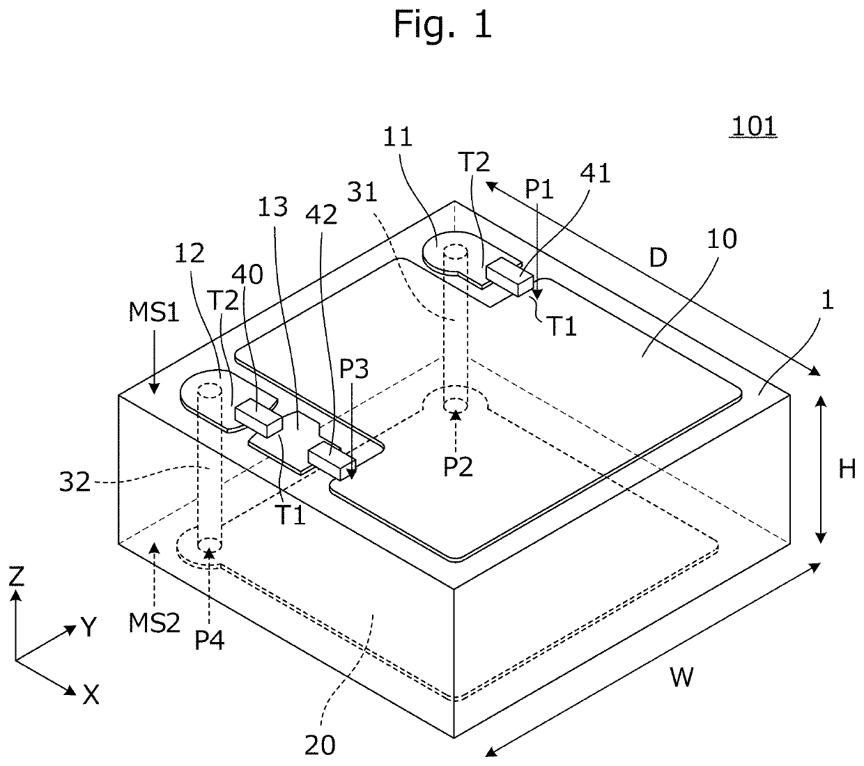
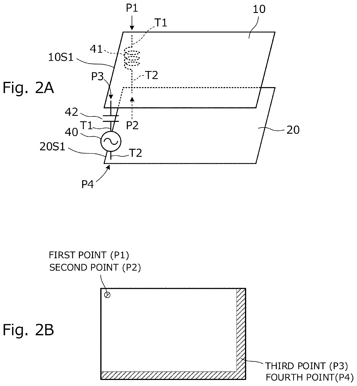
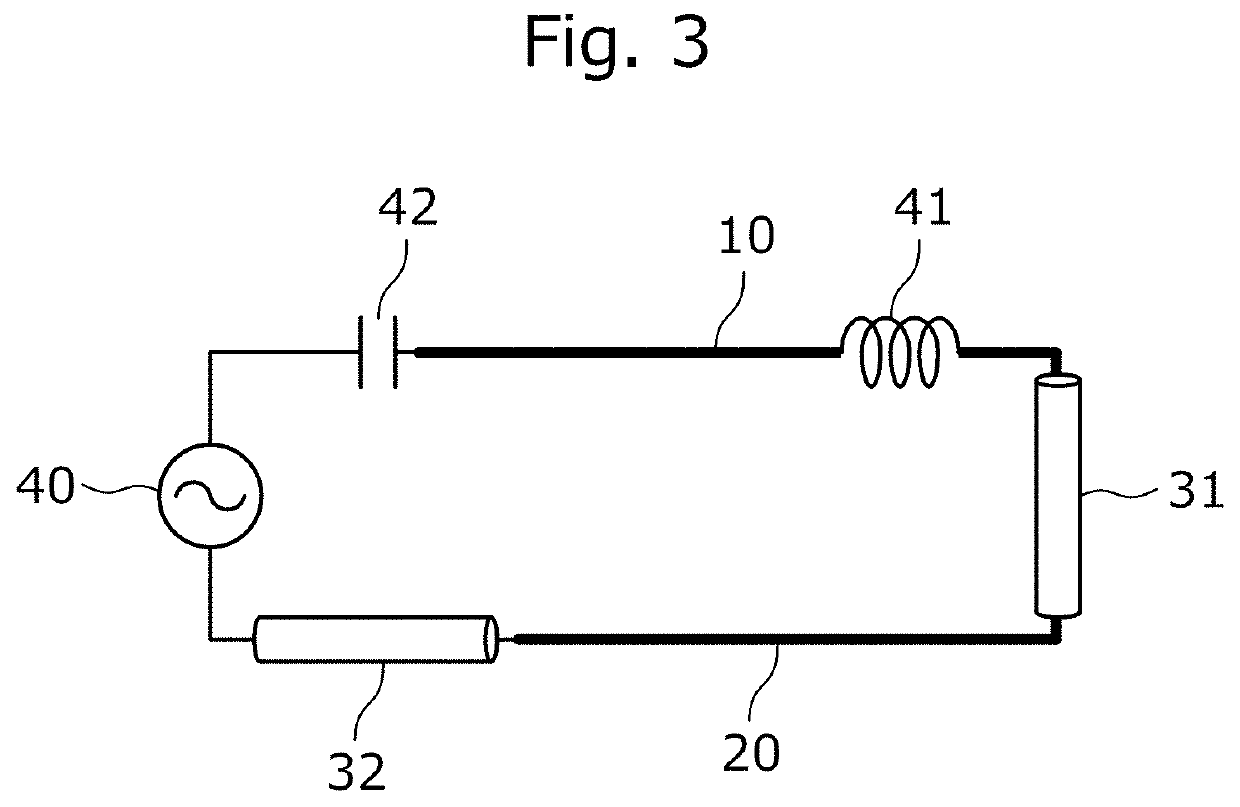
[0071]FIG. 1 is a perspective view of an RFIC module according to a first exemplary embodiment of the present invention. As shown, this RFIC module 101 includes a first planar conductor 10, a second planar conductor 20, an RFIC 40, an inductor 41, and a capacitor 42. In FIG. 1, the RFIC module 101 includes an insulating base material 1 of a rectangular parallelepiped shape, and the first planar conductor 10 is provided on a first principal surface MS1 of the insulating base material 1. The second planar conductor 20 is provided on a second principal surface MS2 of the insulating base material 1. In other words, the first planar conductor 10 and the second planar conductor 20 face in parallel to each other.
[0072]Moreover, electrodes 11, 12, and 13 are provided on the first principal surface MS1 of the insulating base material 1. The electrode 11 is connected to the second planar conductor 20 through a first via conductor 31. The electrode 12 is connected to the second planar conducto...
second exemplary embodiment
[0104]A second exemplary embodiment of the present invention provides an example of an RFIC module that is different in a connection positional relationship of the RFIC 40 and the capacitor 42 from the connection positional relationship of the RFIC module described in the first exemplary embodiment of the present invention.
[0105]FIG. 12 is a perspective view of an RFIC module 102 according to the second exemplary embodiment of the present invention. This RFIC module 102 includes a first planar conductor 10, a second planar conductor 20, an RFIC 40, an inductor 41, and a capacitor 42. In FIG. 12, the RFIC module 102 includes an insulating base material 1 of a rectangular parallelepiped shape, and the first planar conductor 10 is provided on a first principal surface MS1 of the insulating base material 1. The second planar conductor 20 is provided on a second principal surface MS2 of the insulating base material 1.
[0106]Electrodes 11, 12, and 13 are provided on the first principal sur...
third exemplary embodiment
[0110]A third exemplary embodiment of the present invention provides an example of an RFIC module that is different in a connection positional relationship of the capacitor 42 from the connection positional relationship of the RFIC module described in the second exemplary embodiment of the present invention.
[0111]FIG. 14 is a perspective view of an RFIC module 103 according to the third exemplary embodiment. This RFIC module 103 includes a first planar conductor 10, a second planar conductor 20, an RFIC 40, an inductor 41, and a capacitor 42. In FIG. 14, the RFIC module 103 includes an insulating base material 1 of a rectangular parallelepiped shape, and the first planar conductor 10 is provided on a first principal surface MS1 of the insulating base material 1. The second planar conductor 20 is provided on a second principal surface MS2 of the insulating base material 1.
[0112]Electrodes 11 and 12 are provided on the first principal surface MS1 of the insulating base material 1, and...
PUM
 Abstract
Description
Claims
Application Information
 - R&D Engineer
- R&D Manager
- IP Professional
- Industry Leading Data Capabilities
- Powerful AI technology
- Patent DNA Extraction
Browse by: Latest US Patents, China's latest patents, Technical Efficacy Thesaurus, Application Domain, Technology Topic, Popular Technical Reports.
© 2024 PatSnap. All rights reserved.Legal|Privacy policy|Modern Slavery Act Transparency Statement|Sitemap|About US| Contact US: help@patsnap.com


