Eureka AIR delivers breakthrough ideas for toughest innovation challenges, trusted by R&D personnel around the world.

Piezoelectric device

Inactive Publication Date: 2020-03-05
NIHON DEMPA KOGYO CO LTD
View PDF0 Cites 0 Cited by
  • Summary
  • Abstract
  • Description
  • Claims
  • Application Information

AI Technical Summary

Benefits of technology

This patent describes a piezoelectric device that includes a cap, a base plate, and a flat bonding metal film. The cap is a rectangular frame-shaped structure that covers a piezoelectric element. The base plate is a flat plate that contacts the cap's inner peripheral end. The flat bonding metal film is a rectangular frame-shaped structure that overlaps the cap's inner peripheral end. The flat bonding metal film is formed on the base plate's surface and has a second width from its outer to inner peripheral ends. The technical effect of this design is to improve the stability and reliability of the piezoelectric device by preventing damage to the piezoelectric element during mounting and handling.

Problems solved by technology

However, when an external pressure and the like is applied due to an insufficient sealing strength of the piezoelectric device, leakage possibly occurs between an inside of the piezoelectric device and external air.
While enlarging the bonding metal film and the flange surface enhances a bonding strength of the base plate and the metal cap, this causes increase in size of the piezoelectric device.

Method used


Image

  • Piezoelectric device
  • Piezoelectric device
  • Piezoelectric device

Examples


Embodiment Construction

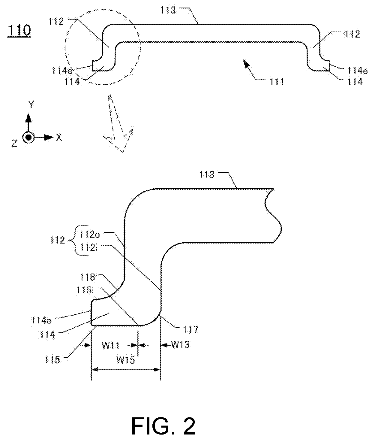
[0012]The following describes an embodiment of the disclosure with reference to the drawings. Each drawing used in the descriptions is merely illustrated schematically for understanding the embodiment, and a size, an angle, a thickness or similar factor is exaggeratedly illustrated. In each drawing used in the descriptions, like reference numerals designate corresponding or identical elements, and therefore such elements will not be further elaborated in some cases. Shapes, dimensions, materials, and similar factor described in the following embodiment are merely preferable examples within the scope of the disclosure.

[0013][Configuration of Piezoelectric Device 100]

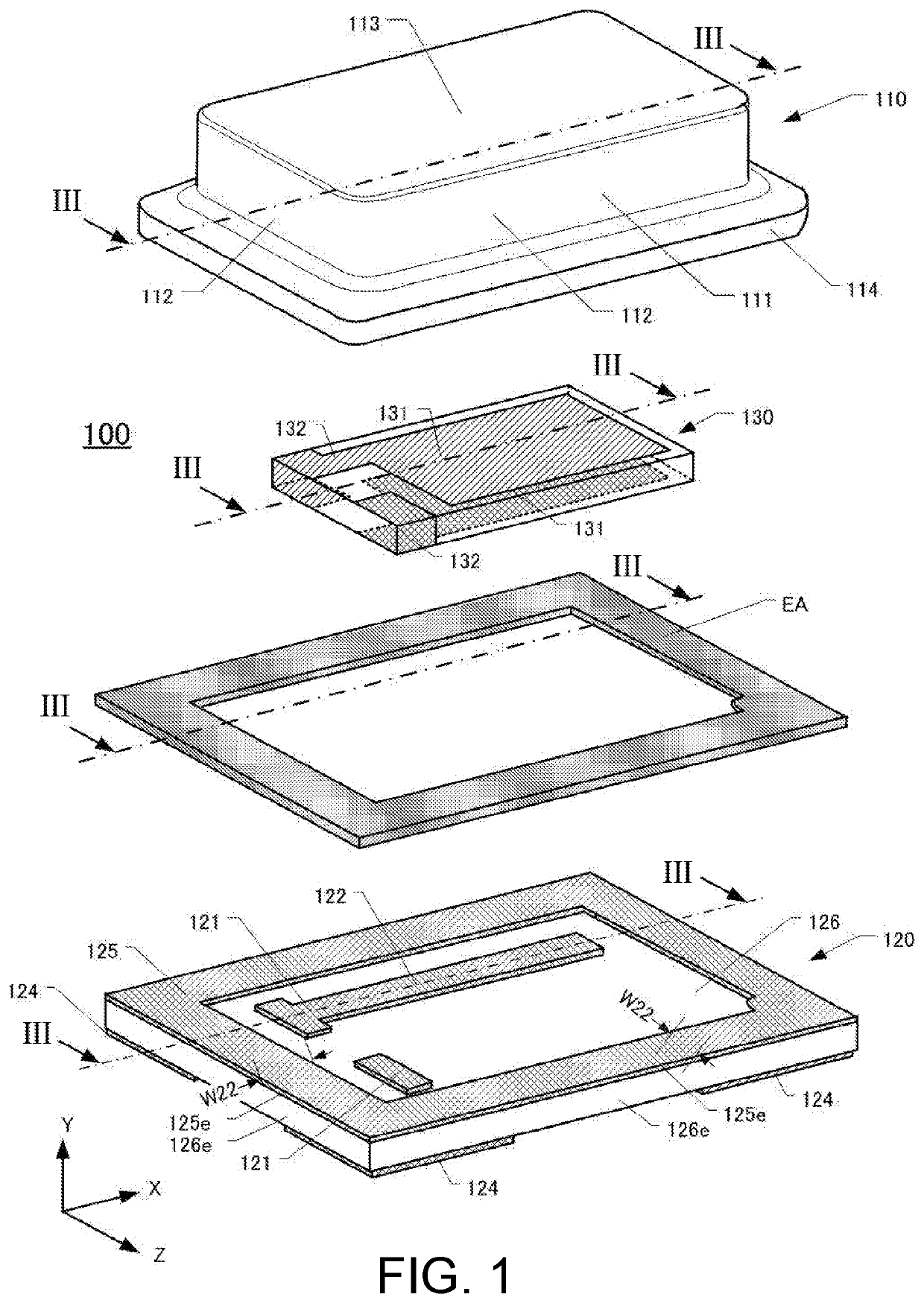
[0014]FIG. 1 is an e exploded perspective view of the piezoelectric device 100. The piezoelectric device 100 includes a cap 110 made of metal, a ceramic base plate 120, and a piezoelectric vibrating piece 130. For the piezoelectric vibrating piece 130, for example, a quartz-crystal vibrating piece of AT-cut, SC-cut, or si...


PUM


Abstract

A piezoelectric device includes a cap, a base plate, and a flat bonding metal film. The cap has a flat plane area having a first width from a first outer peripheral end to a first inner peripheral end. The base plate has a first plane in contact with the cap and a second plane as an opposite surface of the first plane. The base plate has an outer periphery in a shape identical to the rectangular frame shape in plan view. The flat bonding metal film is formed on the first plane. The bonding metal film is formed in a rectangular frame shape in a size overlapping with the plane area. The bonding metal film has a second width from a second outer peripheral end to a second inner peripheral end. The second outer peripheral end is positioned outside the first outer peripheral end.

Description

CROSS-REFERENCE TO RELATED APPLICATIONS[0001]This application claims the priority benefits of Japanese Patent Application No. 2018-160948, filed on Aug. 30, 2018. The entirety of the above-mentioned patent application is hereby incorporated by reference herein and made a part of this specification.TECHNICAL FIELD[0002]This disclosure relates to a piezoelectric device such as a piezoelectric filter, a piezoelectric resonator, and a piezoelectric oscillator.DESCRIPTION OF THE RELATED ART[0003]Piezoelectric devices, such as a piezoelectric filter, a piezoelectric resonator, a piezoelectric vibrating piece, a piezoelectric oscillator, and an acceleration sensor, using a piezoelectric material such as crystal are used in fields in an extremely wide range. One type of such piezoelectric devices is disclosed in, for example, Japanese Unexamined Patent Application Publication No. 2000-134055. This piezoelectric device includes a plate-shaped base plate and a metal cap. The base plate includ...

Claims


Application Information

Patent Timeline
IPC IPC(8): H03H9/10H03H9/19
CPCH03H9/19H03H9/1021H02N2/18
Inventor OKUBO, HIROMIMIZUSAWA, SHUICHI
Owner NIHON DEMPA KOGYO CO LTD
Why Eureka
Eureka Blog
Learn More