
Turbomachine with fan rotor and reduction gearbox driving a low-pressure decompressor shaft

a technology of reduction gearbox and turbine, which is applied in the direction of rotors, machines/engines, mechanical apparatus, etc., can solve the problems of reducing the maximum allowable flight speed of the aircraft, increasing the by-pass ratio, and affecting the aerodynamic operation of the rotor

Active Publication Date: 2020-03-12
SN DETUDE & DE CONSTR DE MOTEURS DAVIATION S N E C M A
View PDF0 Cites 13 Cited by
  • Summary
  • Abstract
  • Description
  • Claims
  • Application Information

AI Technical Summary

Benefits of technology

The invention aims to solve various problems of the prior art by proposing an architecture for a low-pressure turbine coupled with a slow fan rotor. This includes a reduction gearbox interposed within the fan hub, a fairing that ensures an aerodynamic border function around the fan rotor, and a solution integrating standard absorbing acoustic treatments to reduce acoustic emission. This solution ensures high efficiency and low noise levels.

Problems solved by technology

Apart from the dimensional aspects, the increase in by-pass ratio puts the mass of the propulsion system at a disadvantage, via particularly a very significant increase of the mass of the fan casing, sized for the centrifugal retention in the event of blading ejection.
Although, this alternative architecture allows to be rid of constraints of mass and friction drag of the fairing of the secondary portion which is now inexistent, it still poses other issues: first, the absence of a fairing makes the certification context very different with respect to the potential ejection of the low pressure rotor blade and requires taking into account more complex technologies on the rotor (a “fail safe” blade according for example), second, the absence of a fairing around the low pressure portion makes the aerodynamic operating of its rotor very sensitive to the variations in flight conditions (especially speed), and reduces the aircraft's maximum allowable flight speed.
Finally, the absence of a fairing induces a specific flow rate that is much lower than a solution with a fairing, leading, for a given thrust level, to much more important external dimensions than a solution with a fairing, thereby, aggravating the installation difficulty on the airframe structure on the dimensional plane.
The total suppression of the fairing of the low pressure portion, although, it is considered an acceptable option for average-size aircrafts which fly at low to medium speeds (regional / short haul flights), it seems to induce too many drawbacks for usage on higher thrust classes (medium and long haul), for which the flight speed capacity is hardly open to discussion as far as operators are concerned.
However, this document does not at all take into consideration fans with very low pressure ratios.

Method used


Image

  • Turbomachine with fan rotor and reduction gearbox driving a low-pressure decompressor shaft
  • Turbomachine with fan rotor and reduction gearbox driving a low-pressure decompressor shaft
  • Turbomachine with fan rotor and reduction gearbox driving a low-pressure decompressor shaft

Examples


Embodiment Construction

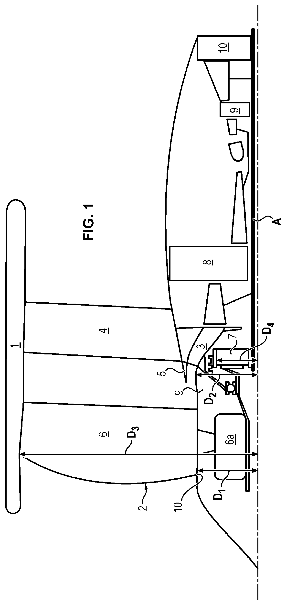
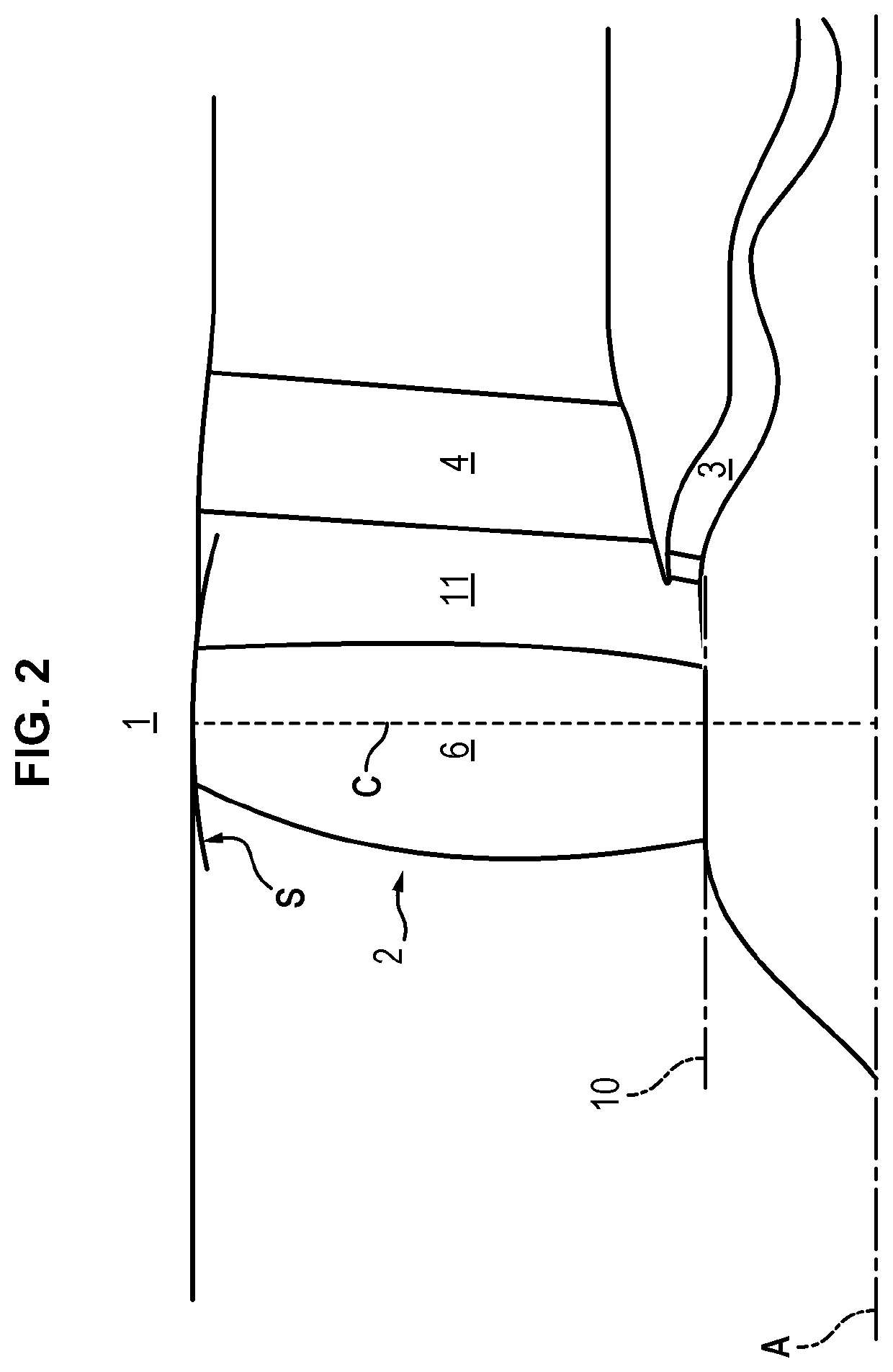
[0059]The turbomachine T illustrated on FIG. 1 exhibits an architecture with a ducted fan having an ultra high by-pass ratio, called UHBR.

[0060]It includes a nacelle 1, a fan rotor 2, as well as a primary stream 3, defined in a casing 5.

[0061]It is also represented on FIG. 1 an inter-compressor casing 8 of the turbomachine, an inter-turbine casing 9, as well as an exhaust casing 10.

[0062]The nacelle 1 is compact and particularly of reduced length. In particular, it does not integrate air inlets or secondary nozzles upstream or downstream of the fan.

[0063]Neither does it integrate a thrust reversal mechanism.

[0064]Its main functions are to ensure the turbomachine aerodynamic fairing and the retention of the fan vanes / blades and is dimensioned solely for this purpose.

[0065]A rectifier assembly 4 is interposed between the nacelle 1 and the casing 5 and allows to hold said nacelle 1.

[0066]In a possible embodiment, a portion of the nacelle 1 can be made jointly with an already existing s...


PUM


Abstract

A turbomachine comprising a ducted fan, a low-pressure turbine shaft and a reduction gearbox housed in a casing between the fan and the low-pressure turbine shaft, the fan rotor supplying airflow to a primary stream and a secondary stream and comprising a hub of diameter D1, wherein—the diameter D3 of the fan rotor is greater than 82 inches (2.08 metres),—the pressure ratio of the fan is between 1.10 and 1.35, the turbomachine comprises a low-pressure compressor separate from the fan, the reduction gearbox being interposed between the fan rotor and a turbine shaft of the low-pressure compressor, and wherein the reduction gearbox casing has an outside diameter D2 greater than the diameter D1 of the hub, the pitch diameter D4 of the reduction gearbox ring being between 0.15 and 0.35 times the fan rotor diameter.

Description

TECHNICAL FIELD AND PRIOR ART[0001]The present invention pertains to the field of turbomachines.[0002]Searching to minimise polluting emissions linked to air transport also involves improving the propulsion system efficiency, and more particularly the propulsion yield characterising the efficiency with which the energy that is communicated to the air that crosses the engine, is converted into useful thrust force.[0003]The elements first affecting this propulsion efficiency are those linked to the low pressure portions of the propulsion system, these immediately contribute to generating thrust: low pressure turbine, low pressure transmission system, fan rotor and secondary channel guiding the flow of the latter.[0004]The guiding principle which is known for improving propulsion efficiency consists in reducing the fan compression rate, thereby, reducing the engine output flow speed and the losses by kinetic energy linked thereto.[0005]One of the main consequences of this reduction in ...

Claims


Application Information

Patent Timeline
Patent Type & Authority Applications(United States)
IPC IPC(8): F02C7/36
CPCF02C7/36F05D2240/20F05D2260/40F02K3/06F05D2260/40311Y02T50/60F01D11/08F01D7/00
Inventor LEMARCHAND, KEVIN MORGANECHARIER, GILLES ALAIN MARIENOWAKOWSKI, NATHALIETANTOT, NICOLAS JÉRÔME JEANDUBOSC, MATTHIEU PIERRE MICHELMAYHEW, DOMINIQUE GERHARDT
Owner SN DETUDE & DE CONSTR DE MOTEURS DAVIATION S N E C M A
Learn More