Wearable Inductive Damping Sensor

a technology of inductive damping and sensor, which is applied in the field of wearable inductive damping sensors, can solve the problems of causing a large amount of pain, affecting the normal operation of the body, and affecting the normal operation of the body, and human beings may suffer from a hemorrhagic strok

Active Publication Date: 2020-03-12
CALIFORNIA INST OF TECH
View PDF0 Cites 2 Cited by
  • Summary
  • Abstract
  • Description
  • Claims
  • Application Information

AI Technical Summary

Benefits of technology

[0008]Techniques are described for a non-invasive detection of a health condition of an organ. In an example, a sensor system is used for the non-invasive detection. The sensor system includes an inductive damping sensor including a coil that has an inductance and a resistance. The inductive damping sensor is configured to generate a magnetic field based on the coil, measure at least one of the inductance or the resistance based on a counteracting magnetic field from an organ located within the magnetic field, and output data that indicates the at least one of the inductance or the resistance. The sensor system also includes a computer system communicatively coupled with the inductive damping sensor and including a processor and a memory. The memory stores computer-readable instructions that, upon execution by the processor, cause the computer system to receive the data and determine a health condition of the organ based on the least one of the inductance or the resistance of the coil as indicated by the data.

Problems solved by technology

Many of the diseases can be fatal or cause a great amount of pain.
However, many of such technologies can be complex to use or even invasive.
For example, a human may suffer from a hemorrhagic stroke, in which a vessel ruptures in the brain and leads to excessive bleeding.
The bleeding can compress areas of the brain and prevent adequate perfusion, leading to cell death.
In both examples, the complexity of the diagnosis techniques typically necessitates physical examination by a trained physician.
In addition, the complexity can hinder the capability of continuous monitoring outside of the physical examination and, thus, the capability of performing preventive treatment.

Method used


Image

  • Wearable Inductive Damping Sensor
  • Wearable Inductive Damping Sensor
  • Wearable Inductive Damping Sensor

Examples


Embodiment Construction

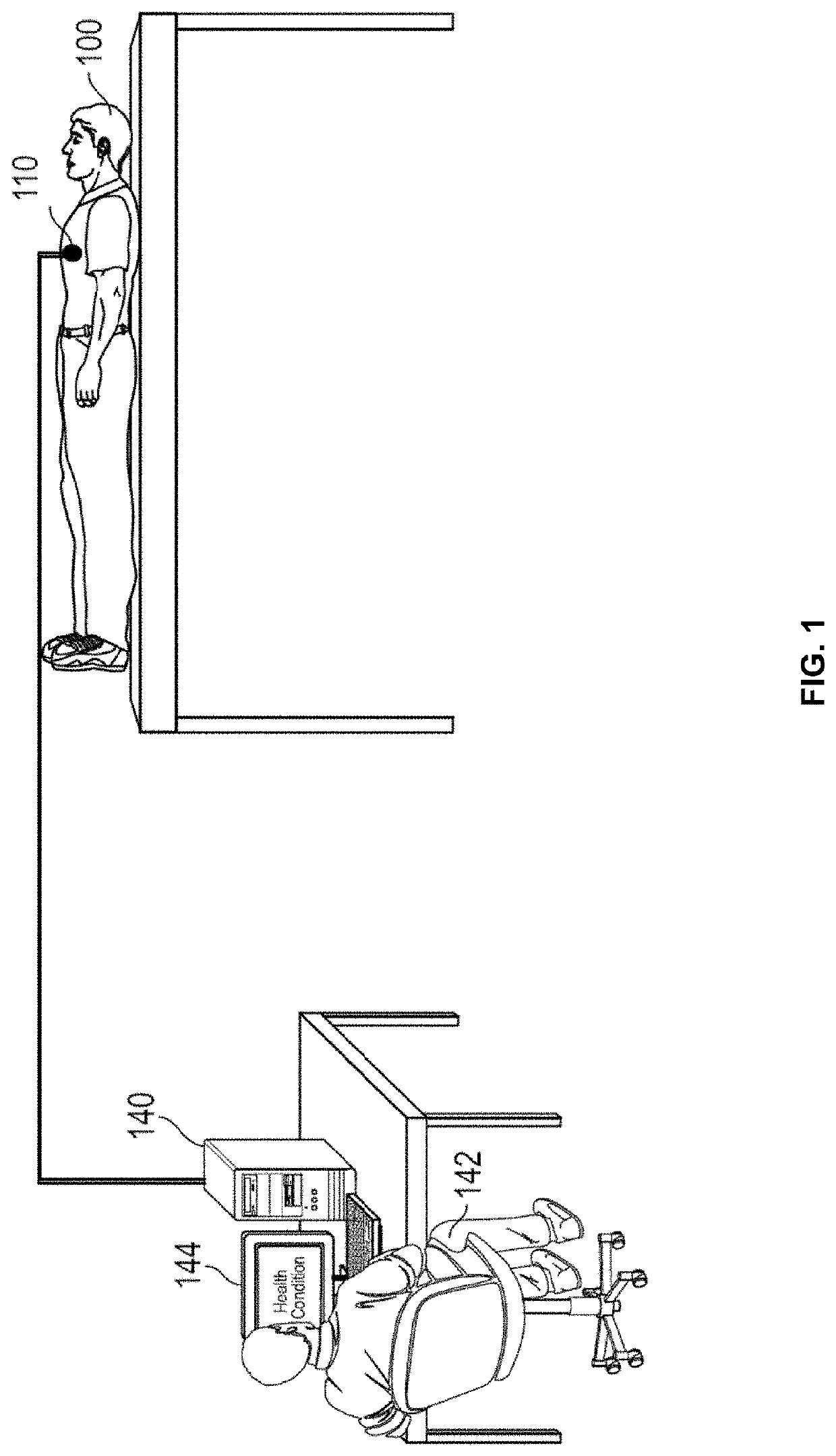
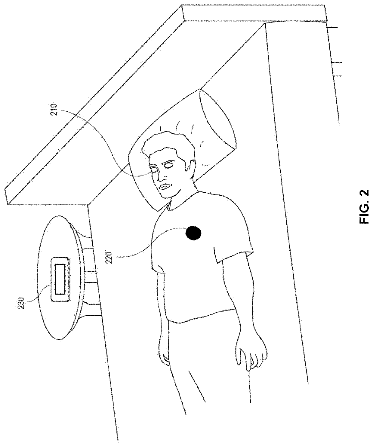
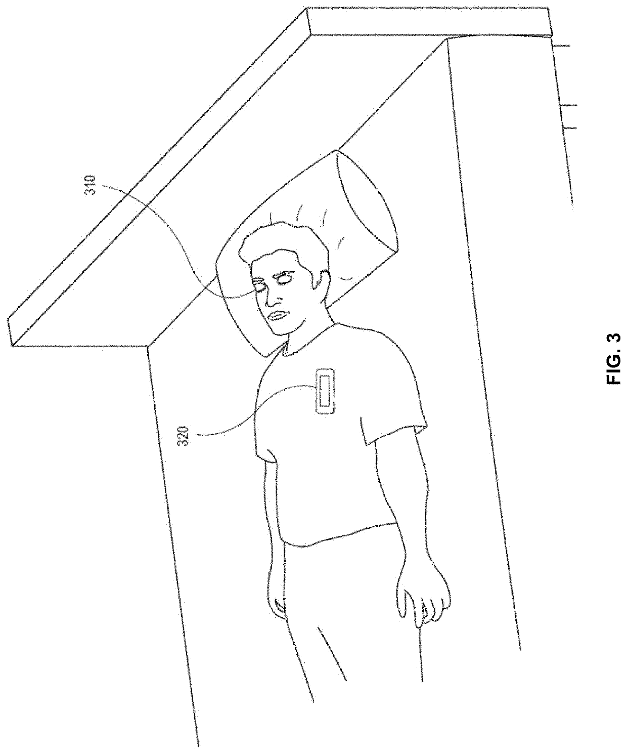
[0045]Generally, diagnosis techniques are described herein. Particularly described are exemplary diagnosis techniques that rely on a sensor system to diagnose a health condition of a subject, such as a human. The sensor system resolves many of the complexity issues of existing diagnosis system and, if needed, may be partially or fully worn or attached to the subject to allow continuous monitoring of the health condition.

[0046]In embodiments, an organ of a subject may be associated with a known conductivity. A change to the conductivity can indicate a health condition of the organ. For example, the organ has a relatively low electrical conductivity, whereas fluid, such as blood or urine, can have a relatively high electrical conductivity. The health of the organ can be diagnosed by measuring its electrical conductivity. In particular, the measured conductivity is expected to be low for a healthy organ. However, if the measured conductivity is high, the organ may not be healthy and th...


PUM

PropertyMeasurementUnit
diameteraaaaaaaaaa
diameteraaaaaaaaaa
resonance frequencyaaaaaaaaaa

Abstract

Techniques are described for a non-invasive detection of a health condition of an organ. In an example, the electrical conductivity of the organ reflects the organ's health of. An inductive damping sensor can be used to detect the organ's electrical conductivity and, thus, its health. The inductive damping sensor can be placed in proximity of the organ such as the organ is within the magnetic field generated based on a coil of the inductive damping sensor. The conductivity of the organ impacts the inductance and the resistance of the coil. Hence, the inductance and/or resistance of the coil can be measured, where the measurements can be associated with the health of the organ.

Description

CROSS-REFERENCES TO RELATED APPLICATIONS[0001]This application claims the benefit of U.S. Provisional Application No. 62 / 730,351, filed Sep. 12, 2018, the contents of which are hereby incorporated in its entirety for all purposes.STATEMENT AS TO RIGHTS TO INVENTIONS MADE UNDER FEDERALLY SPONSORED RESEARCH AND DEVELOPMENT[0002]NOT APPLICABLEBACKGROUND[0003]By nature, living beings are subject to diseases. Many of the diseases can be fatal or cause a great amount of pain. Tremendous effort has been invested in developing technologies to diagnose and treat the diseases. However, many of such technologies can be complex to use or even invasive.[0004]For example, a human may suffer from a hemorrhagic stroke, in which a vessel ruptures in the brain and leads to excessive bleeding. The bleeding can compress areas of the brain and prevent adequate perfusion, leading to cell death. To diagnose whether the hemorrhagic stroke actually occurred or not, the human can be placed inside a magnetic ...

Claims


Application Information

Patent Timeline
Patent Type & Authority Applications(United States)
IPC IPC(8): G16H20/30G16H50/20A61B5/04A61B5/00G01N27/04G01R27/26
CPCA61B5/04008A61B5/7278A61B2562/0223A61B5/04005G01N27/041G16H50/20A61B5/04007G01R27/2611G16H20/30G16H40/63G01R27/02G01R15/183A61B5/243A61B5/245A61B5/242
Inventor TAI, YU-CHONGCHOU, TZU-CHIEHSHAHRESTANI, SHANE S.
Owner CALIFORNIA INST OF TECH
Why Eureka
Try Eureka