Inductor
- Summary
- Abstract
- Description
- Claims
- Application Information
AI Technical Summary
Benefits of technology
Problems solved by technology
Method used
Image

Examples
embodiments
First Embodiment
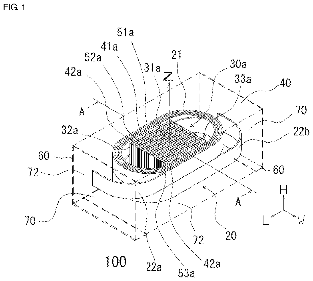
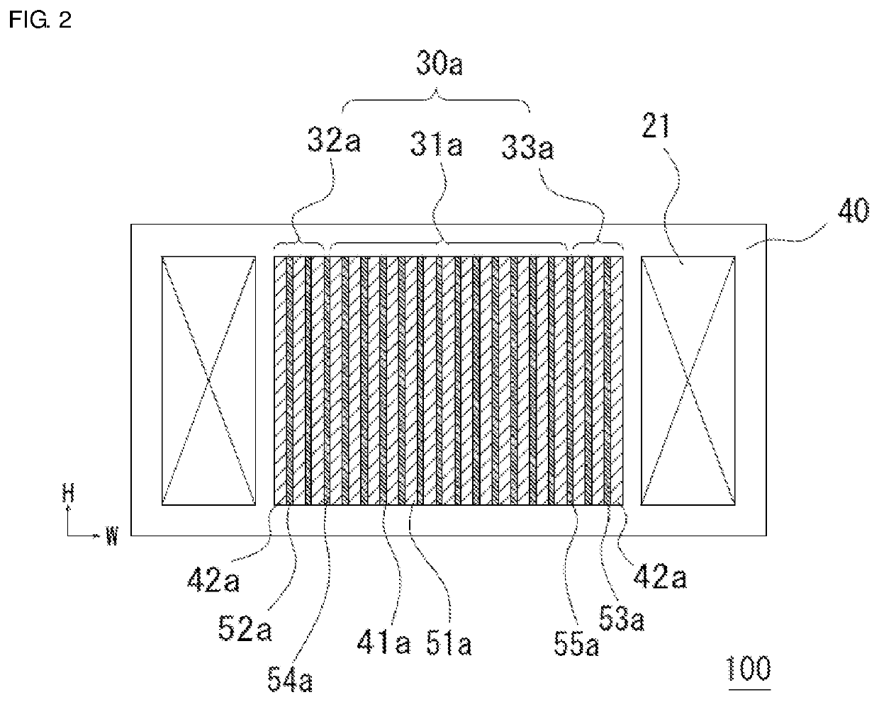
[0026]An inductor 100 of first embodiment will be described while referring to FIGS. 1 and 2. FIG. 1 is a schematic transparent perspective view illustrating first embodiment of the inductor 100. FIG. 2 is a schematic sectional view of the inductor 100 along a plane that is parallel to a winding axis of the coil and taken along line A-A in FIG. 1.
[0027]As illustrated in FIG. 1, the inductor 100 includes a coil 20 consisting of a wound part 21 and a pair of extending parts 22a and 22b that extend from the wound part 21; a core 30a that is surrounded by the wound part 21 of the coil 20; an element body 40 that contains the coil 20 and the core 30a; and a pair of outer terminals 60 that are respectively electrically connected to the extending parts 22a and 22b. The outer peripheral shape of the wound part 21 as seen in a winding axis direction Z is a substantially elliptical or oval shape having a long axis and a short axis. The element body 40 has a bottom surface that...
second embodiment
[0039]An inductor of second embodiment has substantially the same configuration as the inductor 100 of first embodiment except that the relative magnetic permeability of the second magnetic layers is larger than the relative magnetic permeability of the first magnetic layers. In the inductor of second embodiment, the electrical resistivity of the second magnetic layers may be substantially identical to the electrical resistivity of the first magnetic layers.
[0040]Table 2 illustrates the results of a simulation of the inductance value and eddy current loss Pe of inductors in which the configuration of a multilayer part forming a core was varied, the multilayer part being formed by stacking a second multilayer part composed of magnetic layers b and insulating layers, a first multilayer part composed of magnetic layers a and insulating layers, and a third multilayer part composed of the magnetic layers b and insulating layers in this order, where the DC superimposed current was 0 A, th...
third embodiment
[0045]An inductor of third embodiment has substantially the same configuration as the inductor 100 of first embodiment except that a relationship that the product of the electrical resistivity and the relative magnetic permeability of the second magnetic layers is larger than the product of the electrical resistivity and the relative magnetic permeability of the first magnetic layers is satisfied. The first magnetic layers and the second magnetic layers have identical thicknesses and relative magnetic permeabilities. In the inductor of third embodiment, the first magnetic layers and the second magnetic layers may have different electrical resistivities and relative magnetic permeabilities from each other, the first magnetic layers and the second magnetic layers may have substantially identical electrical resistivities and different relative magnetic permeabilities from each other, or the first magnetic layers and the second magnetic layers may have substantially identical relative m...
PUM
 Abstract
Description
Claims
Application Information
 - Generate Ideas
- Intellectual Property
- Life Sciences
- Materials
- Tech Scout
- Unparalleled Data Quality
- Higher Quality Content
- 60% Fewer Hallucinations
Browse by: Latest US Patents, China's latest patents, Technical Efficacy Thesaurus, Application Domain, Technology Topic, Popular Technical Reports.
© 2025 PatSnap. All rights reserved.Legal|Privacy policy|Modern Slavery Act Transparency Statement|Sitemap|About US| Contact US: help@patsnap.com