Device for performing or preparing for a mitral valve annuloplasty by a transfemoral approach

a technology of mitral valve and annuloplasty, which is applied in the field of devices for performing or preparing an annuloplasty of the hearts mitral valve by transfemoral approach, can solve the problems of long and difficult procedure of mitral valve annuloplasty, and requires a difficult and invasive surgical procedur

Active Publication Date: 2020-04-02
CMINOV +1
View PDF0 Cites 5 Cited by
  • Summary
  • Abstract
  • Description
  • Claims
  • Application Information

AI Technical Summary

Problems solved by technology

Mitral annuloplasty is a long and difficult procedure that requires the opening of one of the heart chambers and the chest cavity with extracorporeal blood circulation.
The device of the prior art is designed to pass through the chest cavity between two ribs to enter the left ventricle through the apex of the heart, and thus requires a difficult and invasive surgical procedure.

Method used


Image

  • Device for performing or preparing for a mitral valve annuloplasty by a transfemoral approach
  • Device for performing or preparing for a mitral valve annuloplasty by a transfemoral approach
  • Device for performing or preparing for a mitral valve annuloplasty by a transfemoral approach

Examples


second embodiment

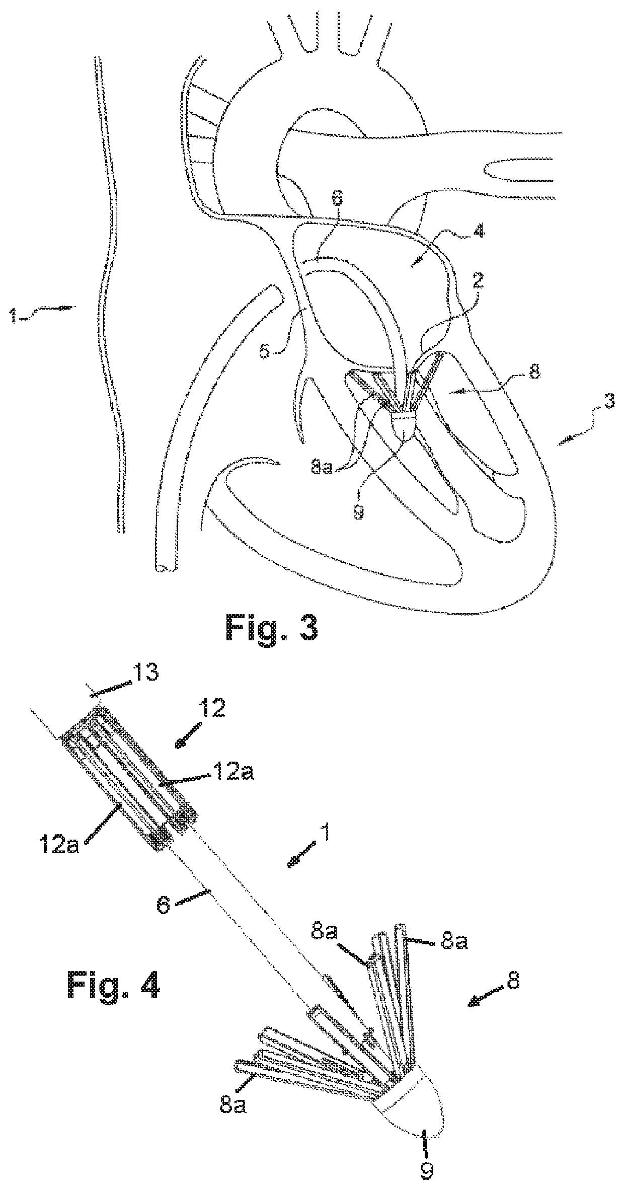
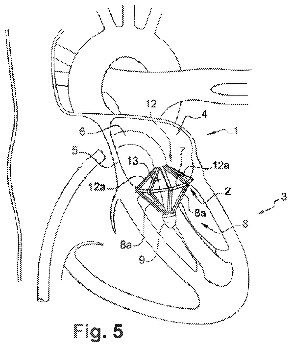
[0061]In the invention, each of the free ends of the arms (8a) of the bearing member (8) is shaped, in the form of a loop for example, to receive a piece of fabric (10) made of felt or Teflon, known to a person skilled in the art as a “pledget”. The fabric pieces (10) are intended to be laid under the mitral annulus (2) and fixed by sutures (11) to counter-bear against the reinforcement ring (7), as described below.

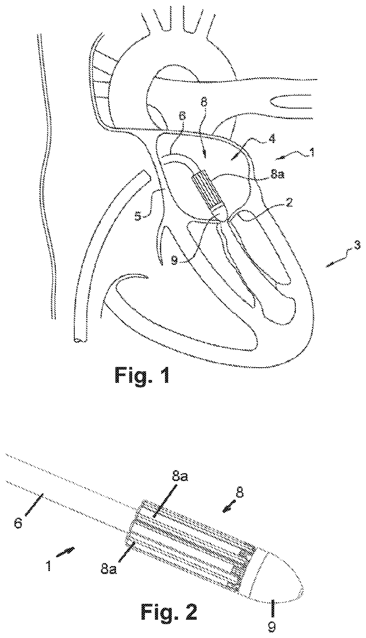
[0062]In both embodiments, the arms (8a) of the bearing member (8) are deployed manually, either together or selectively and independently of each other, to facilitate passage through the mitral cords and adapt to the geometry of the mitral annulus (2). To adapt more closely to the geometry of the mitral annulus (2), which is not necessarily circular, the arms (8a) are telescopic to offer varying lengths.

[0063]In a first variant, the arms (8a) can be deployed by mechanical means (not shown) that are included in the control means. For example, a control knob can be screwed...

first embodiment

[0068]In the first embodiment, and with reference to FIGS. 6 to 9, the reinforcement ring (7) is attached from below the mitral valve and the sutures (11) are extracted from the arms (8a) of the bearing member (8), which thus form the means (14) for extracting sutures (11). Thus each arm (8a) comprises an internally mounted needle (15) with the translation displacement ability to extend beyond the free end of the arms (8a), and release the sutures (11) to attach the reinforcement ring (7). The needles (15) are shaped to allow the sutures (11) extending from the needle (15) to be engaged, guided, and held in place.

[0069]In a first example of implementation, the needles (15) are intended to be extracted to pierce the mitral annulus (2) and protrude from the upper side of the mitral annulus (2), opening into the inside of the fingers (12d) and forks (12b) of the corresponding arms (12a) of the counter bearing member (12). Next, each suture (11) in the form of a thread (11a) made of sha...


PUM


Abstract

The device (1) is intended to be positioned in a sealed introducer placed in a femoral vein in order to penetrate the left atrium (4) of the heart (3) by passing through the septal wall (5) thereof. The device comprises an assembly for cooperating with a handle under the control of control means for actuation of the assembly, for placing and fixing a reinforcement ring (7) on the mitral valve (2), said assembly being arranged at the end of a manipulation rod (6) and comprising: a bearing member (8) comprising a plurality of arms (8a) connected pivotably to the end of the rod (6) so as to change, under the action of the control means, from a position folded along the rod (6) to a deployed position spaced apart from the rod (6), in order to bear under the mitral valve (2) in a manner uniformly distributed along the periphery of the mitral valve; a counter-bearing member (12) comprising a plurality of arms (12a), at the free end of which arms (12a) the reinforcement ring (7) is arranged, the arms (12a) are connected pivotably to a support (13) disposed coaxially with respect to the rod (6) in such a way as to change, under the action of the control means, from a position folded along the rod (6) to a deployed position spaced apart from the rod (6), in order to realize the counter-bearing on the mitral valve and to position the reinforcement ring (7); means for removing sutures for fixing the reinforcement ring (7) to the mitral valve.

Description

TECHNICAL FIELD[0001]The invention concerns a device for performing or preparing an annuloplasty of the heart's mitral valve by a transfemoral approach.[0002]In other words, the goal of the annuloplasty is to reduce the caliber of the mitral annulus by shortening, through plication of the small valve attachment, the support point between the commissures. A commissure is understood to be narrowing the perimeter of the posterior part of the mitral annulus by creating points of plication on it, resulting in a reduction in the antero-posterior and side-to-side diameter of the mitral valve.[0003]The invention also finds an advantageous application for the placement of a preventive ring, known as a preparation or attachment ring, on the mitral annulus, intended to subsequently receive a mitral valve implant.DESCRIPTION OF THE PRIOR ART[0004]Mitral annuloplasty is performed as a way to correct a mitral leak, and works by dilating the mitral annulus (with loss of coaptation of the valve mar...

Claims


Application Information

Patent Timeline
Patent Type & Authority Applications(United States)
IPC IPC(8): A61F2/24
CPCA61F2250/0065A61F2/2445A61F2250/0098A61F2220/0008A61F2/2466A61F2220/0016A61F2250/0096A61F2220/0075A61F2230/0093
Inventor VOLA, MARCOPAIN, BERNARD
Owner CMINOV
Why Eureka
Try Eureka