
Submerged compartment fluid transfer system

a fluid transfer system and submerged compartment technology, applied in underwater equipment, passenger handling apparatus, special-purpose vessels, etc., can solve the problems of deteriorating breathing air quality and pressure conditions inside the dissub, increasing pressure in the compartment, and significantly reducing the probability of survival of breathing air at high pressur

Active Publication Date: 2020-04-16
GLOBAL AEROSPACE
View PDF4 Cites 1 Cited by
  • Summary
  • Abstract
  • Description
  • Claims
  • Application Information

AI Technical Summary

Benefits of technology

The patent describes a device that helps control the pressure in a submerged vessel. It allows gas to escape from the vessel and equalize with the surrounding sea pressure. This device can be used in a variety of situations, making it easier to safely and efficiently control pressure in submarines and other underwater systems.

Problems solved by technology

The pressure in the compartment may also increase as a result of venting from high-pressure air banks due to damaged plumbing or crew use of emergency breathing apparatus.
During this time breathing air quality and pressure conditions inside the DISSUB can deteriorate.
Breathing of air at high pressures can significantly diminish the likelihood of survival for DISSUB crew members for three reasons.
First, breathing of air at high pressure increases the solution of nitrogen in nerve membranes (nitrogen narcosis) that can cause impairment or incapacitation, similar to drugs or alcohol.
Second, breathing air at high pressure tends to increase the concentration of oxygen in the body, which can be toxic to the central nervous system, lungs and eyes.
Third, decompression sickness (the bends) caused by rapid decompression upon rescue can cause dissolved gases in the body to come out of solution forming bubbles that can cause severe pain, paralysis or death.
In many cases, a DISSUB could end up in much deeper water than 132 feet, so passive venting of excess air pressure to the surrounding water would not be possible.
Since a rescue-capable DISSUB could be located thousands of feet below the surface at pressures over 60 ata, reducing the pressure inside a DISSUB is a major challenge.
No system currently exists that can be used directly by a DISSUB crew that meets naval requirements for addressing these pressure issues.
Powered compressors capable of forcing air out of the compartment into the surrounding water at such high pressures present numerous challenges.
It is quite possible that whatever accident has disabled the submarine will also have disrupted the power system.
It is not possible for current rescue vessels to dock with a DISSUB in shallow water.

Method used


Image

  • Submerged compartment fluid transfer system
  • Submerged compartment fluid transfer system
  • Submerged compartment fluid transfer system

Examples


second embodiment

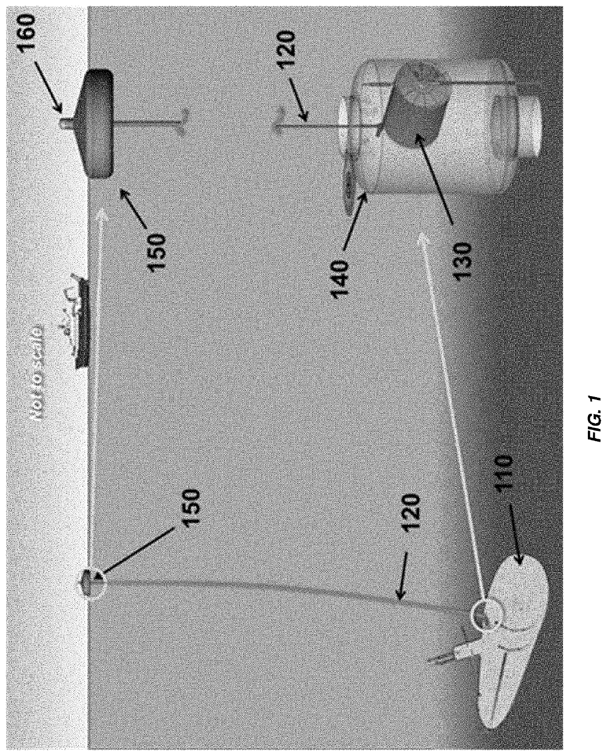
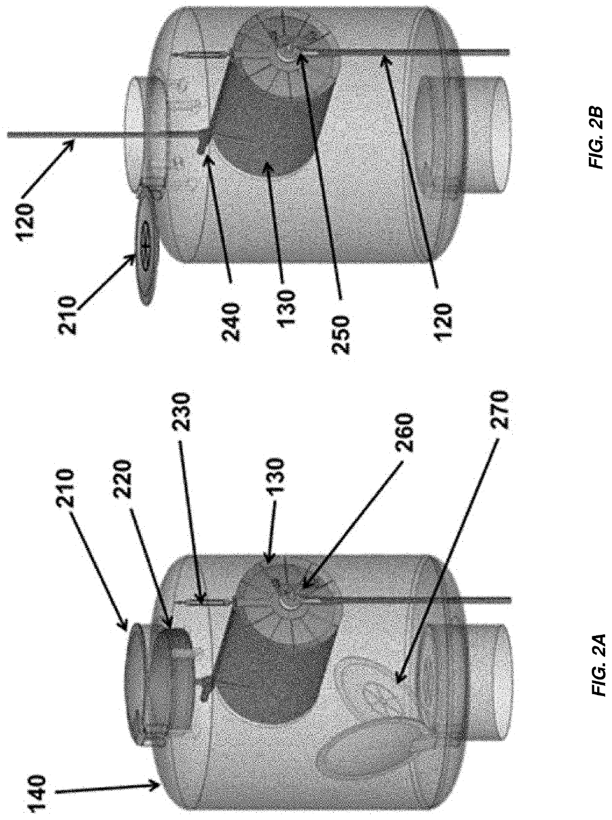
[0056] there is provided an apparatus, comprising a first submerged compartment, a second submerged compartment, and deployable physical connection hardware configured to facilitate transfer of fluid between the first submerged compartment and the second submerged compartment.

third embodiment

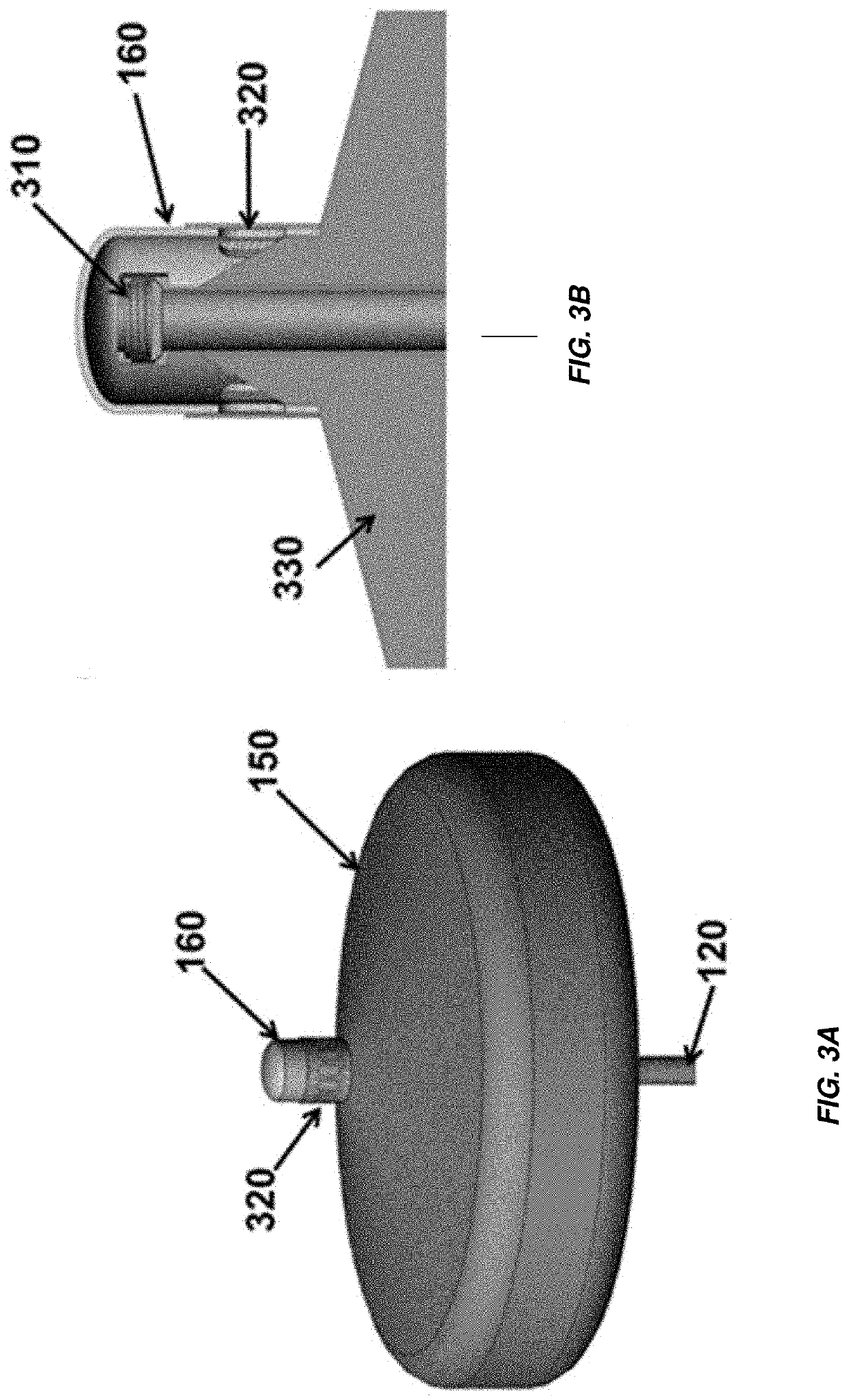
[0057] there is provided an apparatus for use with a submerged compartment comprising physical connection hardware attachable to the submerged compartment wherein the physical connection hardware allows for a transfer of fluid between the submerged compartment and a region near a marine free surface.

[0058]According to a further embodiment, there is provided a method comprising deploying physical connection hardware from a submerged vessel and transferring fluid from a submerged compartment of the submerged vessel using the physical connection hardware.


PUM


Abstract

An apparatus for use with a submerged compartment is presented. The apparatus includes deployable physical connection hardware provided with the submerged compartment. The deployable physical connection allows for a transfer of fluid between the submerged compartment and a region near a marine free surface when deployed. The deployable physical connection hardware comprises a hose in one aspect.

Description

BACKGROUND OF THE INVENTIONField of the Invention[0001]The present invention relates generally to submerged compartments and apparatus associated therewith, and more specifically to devices to transfer fluids between submerged compartments, or between a submerged compartment and a marine free surface such as an air-water interface of the sea, ocean, or body of fresh water.Description of the Related Art[0002]A distressed submarine (DISSUB) on the ocean bottom can, in many instances, have compartments with internal pressures of greater than 1 ata (atmosphere absolute). Flooding of the submarine by water can squeeze the air into a smaller volume, increasing the air pressure inside the compartment. The pressure in the compartment may also increase as a result of venting from high-pressure air banks due to damaged plumbing or crew use of emergency breathing apparatus.[0003]The time required to get rescue crews to a DISSUB can be several days, especially if the DISSUB is in a remote ocean...

Claims


Application Information

Patent Timeline
Patent Type & Authority Applications(United States)
IPC IPC(8): B63G8/41B63B22/02
CPCB63B22/021B63B2022/028B63B2728/00B63G8/41B63B27/24B63C11/00B63B2702/12B63C7/26B63G8/40
Inventor AARON, KIM M.NOCK, KERRY T.
Owner GLOBAL AEROSPACE
Learn More