Eureka AIR delivers breakthrough ideas for toughest innovation challenges, trusted by R&D personnel around the world.

Impedance spectrometer with programmable elements

Active Publication Date: 2020-04-23
CARR WILLIAM N
View PDF0 Cites 0 Cited by
  • Summary
  • Abstract
  • Description
  • Claims
  • Application Information

AI Technical Summary

Benefits of technology

The present invention provides an impedance spectrometer that uses a resonant electromagnetic filter to determine the real and imaginary parts of the wave impedance of a material. The spectrometer can determine the wave impedance of a material by measuring the difference between the RF source signal and the RF response signal at multiple frequencies. The sensor structure can be placed within the material of interest and can be calibrated based on the signal path. The impedance spectrometer can be used in various applications such as soil analysis, agricultural products, and biological materials. The interrogator controlling the sensor structure can be a handheld unit or a networked device. The sensor structure can be calibrated using a resonant electromagnetic filter and a reference material. The impedance spectrometer can be used in a passive or semi-passive RFID system. The technical effects of the invention include improved accuracy in determining the wave impedance of materials and improved sensing of materials using a resonant electromagnetic filter.

Problems solved by technology

It is fundamentally impossible to derive the values of two independent unknown quantities from a single measurement.
In general, sensors such as a capacitance sensor wherein a material of complex permittivity affects the oscillation frequency of an LC resonant circuit, accuracy for measurement of complex impedance is limited due to nonlinear cross modulation effects relating to the real and imaginary parts of material permittivity.
TDR and TDT sensors generally require delay measurements in the picosecond range for useful accuracy. limitations for TDR and TDT sensing include requirement for a length of transmission line adequate to obtain sufficient propagation delay and economic considerations involved with maintaining stability within a picosecond delay timer.

Method used


Image

  • Impedance spectrometer with programmable elements
  • Impedance spectrometer with programmable elements
  • Impedance spectrometer with programmable elements

Examples


Embodiment Construction

Definitions

[0065]The following terms are defined for use in this disclosure and the appended claims:

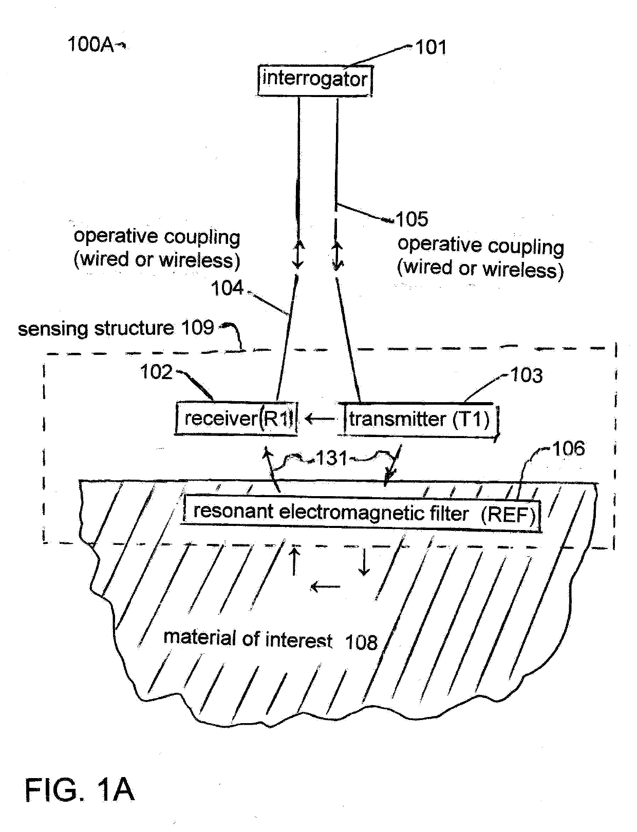
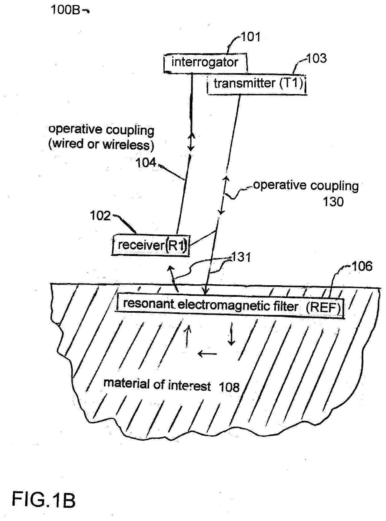
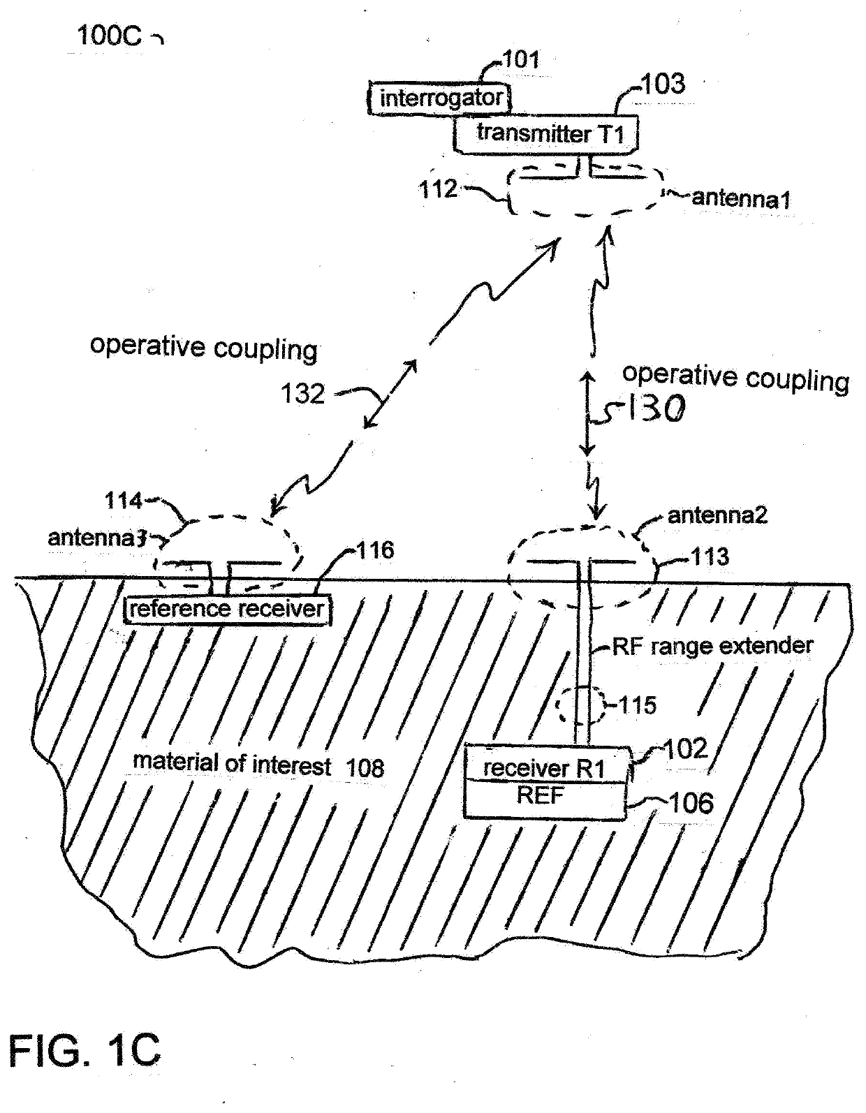
[0066]“interrogator” means the device comprising the control / communications circuits and an impedance calculator. The interrogator controls the sensing structure and may be disposed within a single enclosure or distributed as component parts.

[0067]“transmitter” means the device providing the RF source within the sensing structure with field-coupling into a material of interest.

[0068]“receiver” means the device within the sensing structure receiving the RF response signal coupled from the transmitter as affected by field-coupling with a material of interest.

[0069]“operative coupling” means a wired and / or wireless means of coupling between an interrogator and a sensor structure. The coupling may comprise a digital data link and / or analog RF link. The coupling may comprise a databus digital link and / or a wired databus link.

[0070]“resonant electromagnetic filter” or “REF” means a resonant...


PUM


Abstract

A system and method for sensing wave impedance of a material using an RF power source with a sensor structure comprised of a resonant electromagnetic radiative filter (MEF). The wave impedance is determined by processing a differential RF signal level within an interrogator comprising an impedance calculator. A differential RF signal between a source signal level and a response signal level affected by field coupling of the REF with a material of interest. In embodiments based on frequency scanning transmissometry (FST), the impedance spectrometer determines both the real and imaginary part of the wave impedance of the material. In embodiments the impedance spectrometer comprises an RFID transponder. In embodiments, the interrogator is disposed as payload on a UAV drone. In embodiments, the impedance spectrometer is a node within a communications network.

Description

CROSS REFERENCE TO RELATED APPLICATIONS[0001]This application is a continuation of U.S. patent application Ser. No. 16 / 059,237 filed Aug. 9, 2018. U.S. patent application Ser. No. 16 / 059,237 is a continuation-in-part of U.S. patent application Ser. No. 15 / 507,215 with PCT WO2016 / 033561 filed Aug. 28, 2015 and issued as U.S. Pat. No. 10,101,288 on Oct. 16, 2018.[0002]The underlying concepts, but not necessarily the language, of the following cases are incorporated by reference:[0003]U.S. Provisional Application 62 / 043,376 filed Aug. 28, 2014[0004]U.S. Provisional Application 62 / 106,805 filed Jan. 23, 2015[0005]U.S. Provisional Application 62 / 210,888 filed Aug. 28, 2015[0006]If there are any contradictions or inconsistencies in language between this application and one or more of the cases that have been incorporated by reference that might affect the interpretation of the claims in this case, the claims in the case should be interpreted to be consistent with the language in this case...

Claims


Application Information

Patent Timeline
IPC IPC(8): G01N27/02
CPCG01N27/026G01N33/383G01N27/021G01N27/025G01N33/24G01N33/02G01N33/245
Inventor CARR, WILLIAM N.
Owner CARR WILLIAM N
Why Eureka
Eureka Blog
Learn More