
Light source apparatus and projection-type display apparatus

a technology of projection type and light source, which is applied in the direction of picture reproducers using projection devices, process and machine control, instruments, etc., can solve the problems of inefficient method, wasteful power consumption, and increased apparatus size, so as to reduce light utilization efficiency, efficient cool, and increase the effect of apparatus siz

Inactive Publication Date: 2020-04-30
CANON KK
View PDF0 Cites 3 Cited by
  • Summary
  • Abstract
  • Description
  • Claims
  • Application Information

AI Technical Summary

Benefits of technology

The patent discusses the issue of efficiently cooling light sources that have different operating temperature ranges. One solution is to have separate fixing jigs for each group of light sources, but this increases the size of the apparatus and makes position adjustment difficult between the light sources. The present disclosure addresses this problem by providing a mechanism that can accurately arrange positions between light sources and cool them without wasting cooling capacity, even when different light sources are used. This results in better light utilization efficiency.

Problems solved by technology

However, this method is inefficient because white light generated in this method is characterized in that intensity of only a predetermined wavelength is strong, and it is necessary to cut a predetermined wavelength range by an optical filter to enhance color purity.
Therefore, wasteful power consumption is inefficient, and there is a possibility to cause noises from a cooling fan and the like.
However, such a configuration not only increases a size of an apparatus but also makes position adjustment difficult between the light sources, and thus may reduce light utilization efficiency.

Method used


Image

  • Light source apparatus and projection-type display apparatus
  • Light source apparatus and projection-type display apparatus
  • Light source apparatus and projection-type display apparatus

Examples


Embodiment Construction

[0020]Various exemplary embodiments of the present disclosure will be described in detail below with reference to the attached drawings.

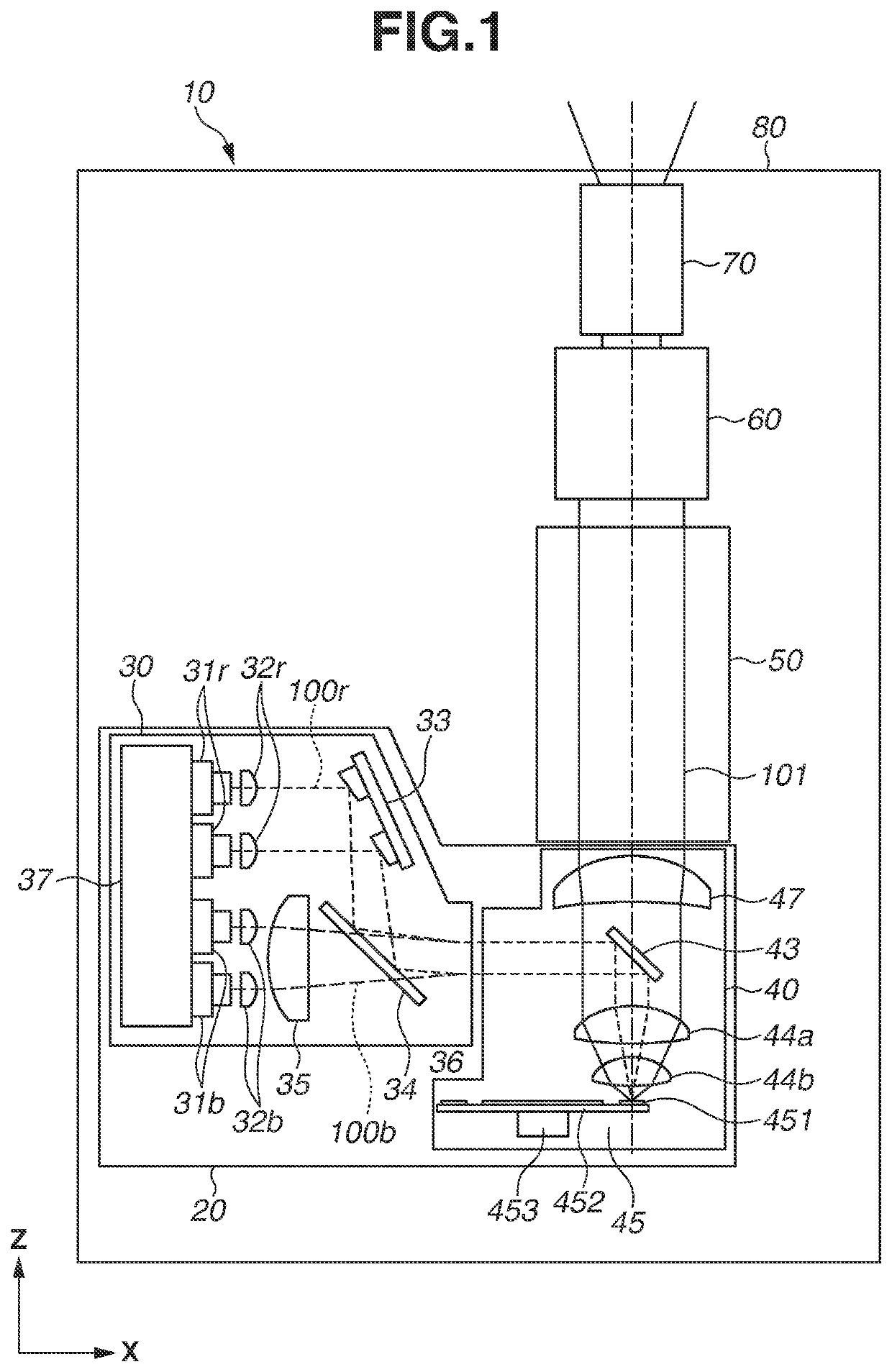
[0021]FIG. 1 illustrates an overall configuration regarding a projector as a projection-type display apparatus according to a first exemplary embodiment of the present disclosure. The present exemplary embodiment is described using a projector which uses a reflective liquid crystal display element as a light modulation element. However, the present exemplary embodiment can be applied to a projection-type display apparatus that uses two or more types of semiconductor light emitting elements having different wavelength bands. Specifically, the present exemplary embodiment can be applied to a projector that uses a light modulation element other than a reflective liquid crystal display element, for example, a digital mirror device (DMD) and a transmissive liquid crystal display element. In the following description, a right direction, an upper direction...


PUM


Abstract

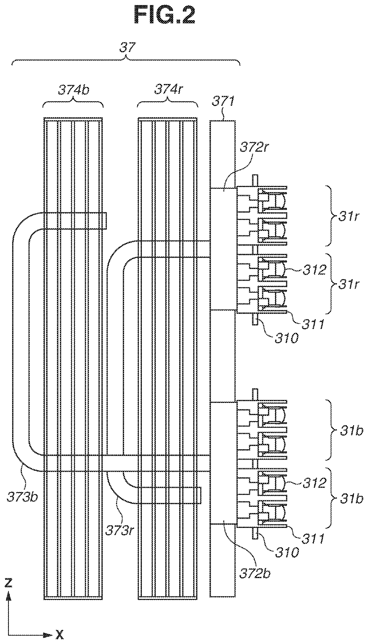
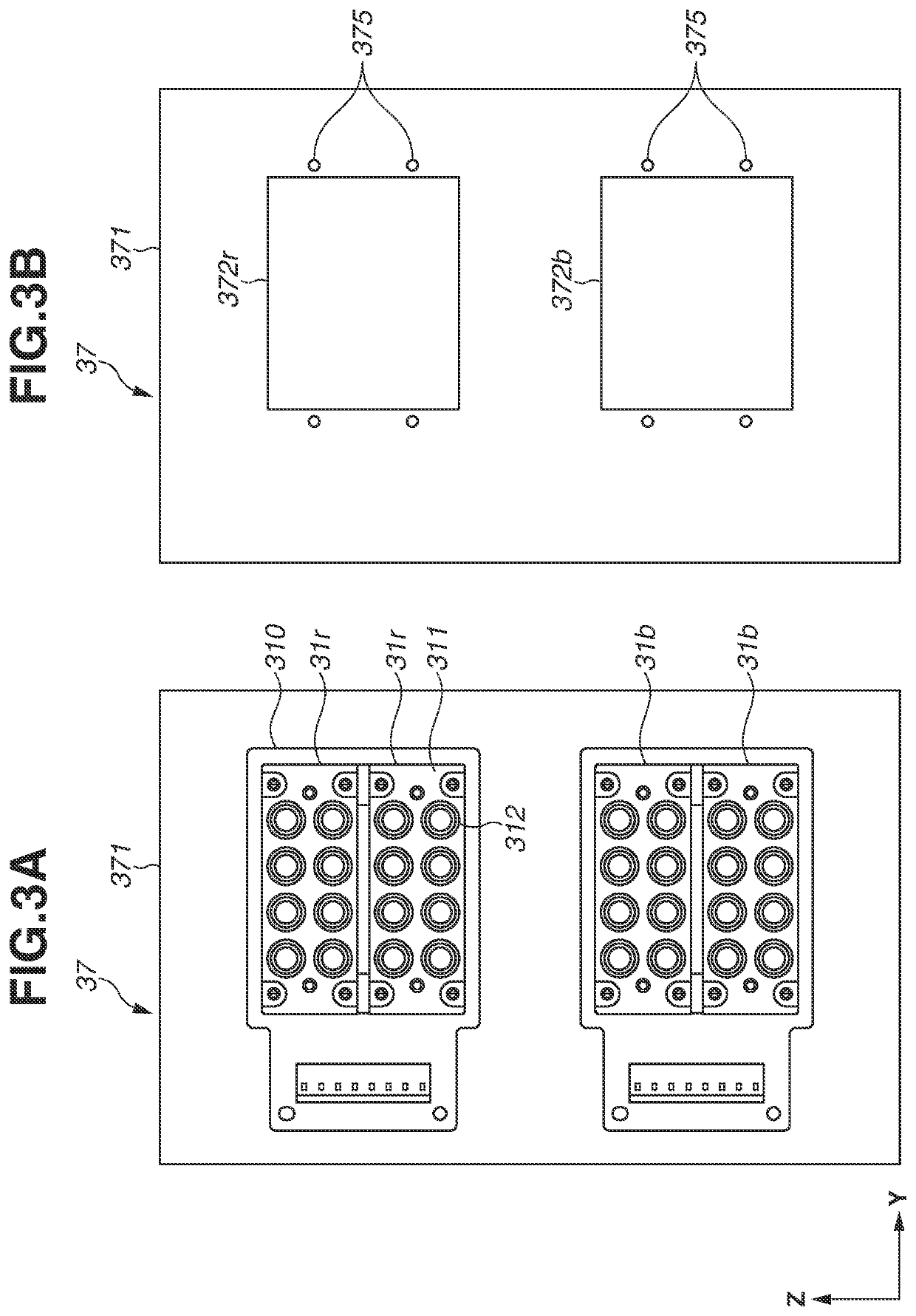
An apparatus useful with or as a light source includes a first light source, a second light source configured to have an operating temperature range different from that of the first light source, a first heat receiving unit configured to receive heat from the first light source, a second heat receiving unit configured to receive heat from the second light source, and a holding member configured to hold the first light source and the second light source, wherein the first light source and the first heat receiving unit are thermally separated from the second light source and the second heat receiving unit.

Description

BACKGROUNDField[0001]The present disclosure relates to a light source apparatus using a plurality of light sources and a projection-type display apparatus.Description of the Related Art[0002]Semiconductor light emitting elements such as laser diodes (hereinbelow, also referred to as LDs) are used as light sources of projection-type display apparatuses, which can realize high durability and high luminance, and white light is generally generated by performing fluorescence conversion on light from blue LDs using a yellow fluorescent material. However, this method is inefficient because white light generated in this method is characterized in that intensity of only a predetermined wavelength is strong, and it is necessary to cut a predetermined wavelength range by an optical filter to enhance color purity. Therefore, generation of white light of which color purity is enhanced using a red LD in addition to a blue LD is considered to efficiently use light from a light source.[0003]LDs whi...

Claims


Application Information

Patent Timeline
Patent Type & Authority Applications(United States)
IPC IPC(8): G03B21/16H04N9/31G03B21/14G03B21/20G05D23/19
CPCG03B21/16G03B21/2033G05D23/1932G03B21/145H04N9/3164H04N9/3161H04N9/3144H04N9/3158
Inventor NODA, TOSHIYUKI
Owner CANON KK
Learn More