Designing a mechanical part with topology optimization

a topology optimization and mechanical part technology, applied in design optimization/simulation, total factory control, instruments, etc., to achieve the effect of increasing mechanical robustness

Active Publication Date: 2020-05-07
DASSAULT SYSTEMES
View PDF2 Cites 13 Cited by
  • Summary
  • Abstract
  • Description
  • Claims
  • Application Information

AI Technical Summary

Benefits of technology

[0007]The method forms an improved solution for designing a modeled object representing a mechanical part formed in a material, subject in use to loads and having one or more constrained boundaries. Notably, based on the finite element mesh and the data associated to the finite element mesh, the method performs a topology optimization and thereby achieves in an efficient manner a design optimized from the mechanical point of view given a constraint relative to global material quantity. In particular, the method yields a result optimized for the part of the loads to which the mechanical part is subject in use, and which are represented by the forces included in the data associated to the mesh. In addition, the method provides for integrating one or more local material quantity constraints to the topology optimization, thereby allowing in each local zone respective to such a local constraint, a control on local material quantity and on the mechanical effects thereof. Furthermore, thanks to the distribution of the one or more local quantity constraints being non-uniform, the method allows a position-wise differentiation of said mechanical effects. Thus, the one or more local material quantity constraints provide a means to compensate for the fact that forces included in the data associated to the mesh cannot and do not represent all the loads to which the mechanical part is subject in use. In particular, the method allows increasing mechanical robustness in view of real future loads that will apply to the mechanical part but that are not integrated directly as forces in the topology optimization problem formulation.

Problems solved by technology

Furthermore, thanks to the distribution of the one or more local quantity constraints being non-uniform, the method allows a position-wise differentiation of said mechanical effects.

Method used


Image

  • Designing a mechanical part with topology optimization
  • Designing a mechanical part with topology optimization
  • Designing a mechanical part with topology optimization

Examples


Embodiment Construction

[0026]The method is computer-implemented. This means that steps (or substantially all the steps) of the method are executed by at least one computer, or any system alike. Thus, steps of the method are performed by the computer, possibly fully automatically, or, semi-automatically. In examples, the triggering of at least some of the steps of the method may be performed through user-computer interaction. The level of user-computer interaction required may depend on the level of automatism foreseen and put in balance with the need to implement user's wishes. In examples, this level may be user-defined and / or pre-defined.

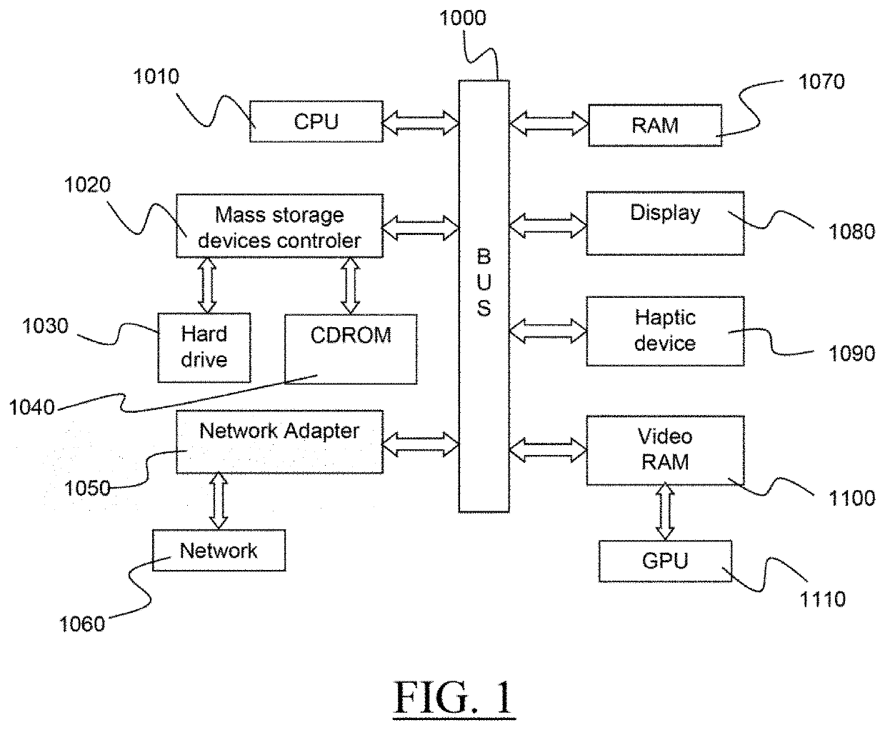
[0027]A typical example of computer-implementation of a method is to perform the method with a system adapted for this purpose. The system may comprise a processor coupled to a memory and a graphical user interface (GUI), the memory having recorded thereon a computer program comprising instructions for performing the method. The memory may also store a database. The mem...


PUM

PropertyMeasurementUnit
global volume fractionaaaaaaaaaa
volume fractionaaaaaaaaaa

Abstract

The disclosure notably relates to a computer-implemented method for designing a modeled object. The method includes obtaining a finite element mesh, data associated to the finite element mesh and a non-uniform distribution of one or more local quantity constraints. The data associated to the finite element mesh include forces, boundary conditions, parameters, and a global quantity constraint. The method also comprises performing a topology optimization based on the finite element mesh, the data associated to the finite element mesh, and the non-uniform distribution. The method improves the design of a modeled object representing a mechanical part by topology optimization.

Description

CROSS-REFERENCE TO RELATED APPLICATIONS[0001]This application claims priority under 35 U.S.C. § 119 or 365 to European Application No. EP 18306445.0, filed Nov. 4, 2018. The entire contents of the above application(s) are incorporated herein by reference.FIELD OF THE INVENTION[0002]The invention relates to the field of computer programs and systems, and more specifically to a method, system and program for designing a modeled object representing a mechanical part.BACKGROUND[0003]A number of systems and programs are offered on the market for the design, the engineering and the manufacturing of objects. CAD is an acronym for Computer-Aided Design, e.g. it relates to software solutions for designing an object. CAE is an acronym for Computer-Aided Engineering, e.g. it relates to software solutions for simulating the physical behavior of a future product. CAM is an acronym for Computer-Aided Manufacturing, e.g. it relates to software solutions for defining manufacturing processes and ope...

Claims


Application Information

Patent Timeline
Patent Type & Authority Applications(United States)
IPC IPC(8): G06F17/50G06F17/18B29C64/393
CPCG06F17/18B29C64/393G06F30/23G06F2119/18B33Y50/02G06F30/17Y02P90/02
Inventor SCHMIDT, MARTIN-PIERRE HUGOORTUZAR DEL CASTILLO, AUXKINPEDERSEN, CLAUS BECH WITTENDORF
Owner DASSAULT SYSTEMES
Why Eureka
Try Eureka