Magnet arrangement for producing a field suitable for nmr in a concave region

a concave region and magnetic field technology, applied in permanent magnets, magnetic bodies, electrical appliances, etc., can solve the problems of mm scans that are difficult to perform, scarring, liver failure, etc., and achieve low field strength, low weight and size, and large volume

Active Publication Date: 2020-05-07
LIVIVOS INC
View PDF0 Cites 0 Cited by
  • Summary
  • Abstract
  • Description
  • Claims
  • Application Information

AI Technical Summary

Benefits of technology

[0008]According to various embodiments of the disclosed technology, a magnet system for use in an external NMR may partially surround an target region within an object of measurement. For example, the object of measurement may be a portion of a subject's body, wherein the subject may be a human or animal patient. The internal region may be an internal organ, such as the liver, kidneys, lungs, etc. The magnet system may have a concave top surface. The concave top surface may accommodate a large object for measurement and may allow the magnet or magnets in the system to partially surround the large object. The concave design may allow the object of measurement to lie deeper within the magnet system than would be possible with a magnet system having a flat top surface. The magnet system may be designed to generate a larger volume of magnetic field having properties suitable for NMR. These properties may include a more homogeneous magnetic field projected within the target region, low field strength, relatively low weight and size, and / or other advantages over the types of magnet systems used for NMR and MM systems.
[0010]In some examples, the magnet system or kit may include two or more permanent magnets. The permanent magnets may have angled, tapered, slanted, or curved top surfaces. The magnets may be arranged such that the magnet systems or kit has a V-shaped configuration or concave top surface. The magnets may be placed so as to form a gap between them. In some examples, magnets or magnetic material may be located in the gap. The additional magnets or magnetic material may be employed to adjust the strength of the magnetic field at a particular location in a space external to the magnet system. The additional magnets or magnetic material may be employed to improve the uniformity of the magnetic field at a particular location. The magnets or magnetic material may be employed to minimize distortion of the magnetic field at a particular location. The magnets or magnetic material may be employed to alter other features or properties of the magnetic field.
[0014]In some embodiments, an iron backing plate or backplane may be included in the magnet system or kit. The iron backplane may function as a mirror plane and may increase the effectiveness of the magnets in the system or kit in producing a magnetic field with desirable properties at a particular location. The iron backplane may minimize the magnitude and effect of fringe fields. The backplane may be designed in a U-shaped configuration. For example, the U-shaped configuration may better accommodate the object of measurement in the magnet system or kit.
[0017]Optimization may refer to generating a field at a value suitable for use in medical NMR techniques. In some examples, the field strength is low, i.e., less than 1 Tesla. Optimization may include homogenizing a magnetic field at a selected target region over a volume of interest. It may refer to minimizing distortion and / or variance of a magnetic field at a target region over a volume of interest.

Problems solved by technology

This excess fat can cause liver inflammation, scarring, and in severe cases liver failure.
Unfortunately, MM scans can be difficult to perform and are expensive relative to other techniques.
This experience can be especially uncomfortable for those with claustrophobia.
Additionally, the MM machine is very loud and it can sometimes take longer than an hour to complete measurement.
Studies into performing analysis using low field-strength NMR have been unreliable due to difficulties in producing a uniform magnetic field, among other problems.
External NMR and MM devices also generally employ magnet designs that are large, heavy, of significant size, weight, and cost.
It is particularly challenging to design a magnet for use in making measurements from volumes of interest in the interiors of much larger objects.

Method used


Image

  • Magnet arrangement for producing a field suitable for nmr in a concave region
  • Magnet arrangement for producing a field suitable for nmr in a concave region
  • Magnet arrangement for producing a field suitable for nmr in a concave region

Examples


Embodiment Construction

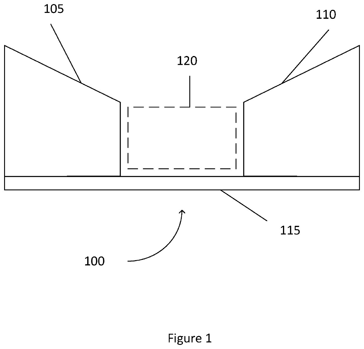
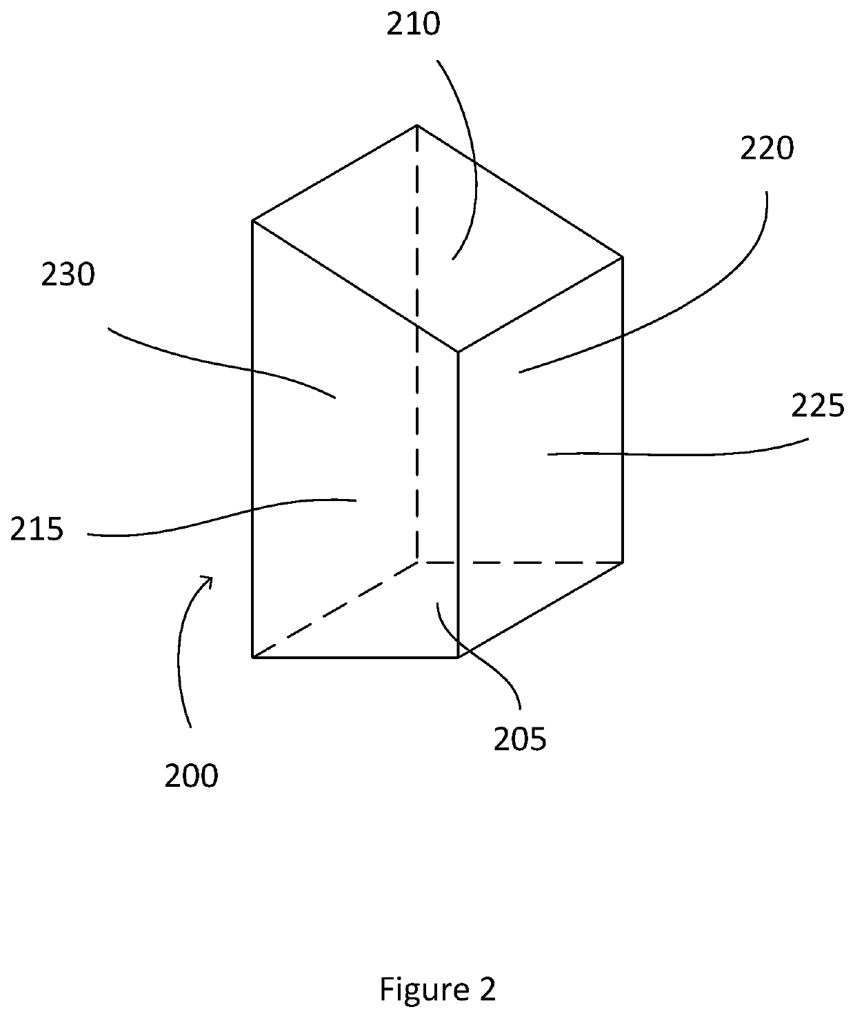
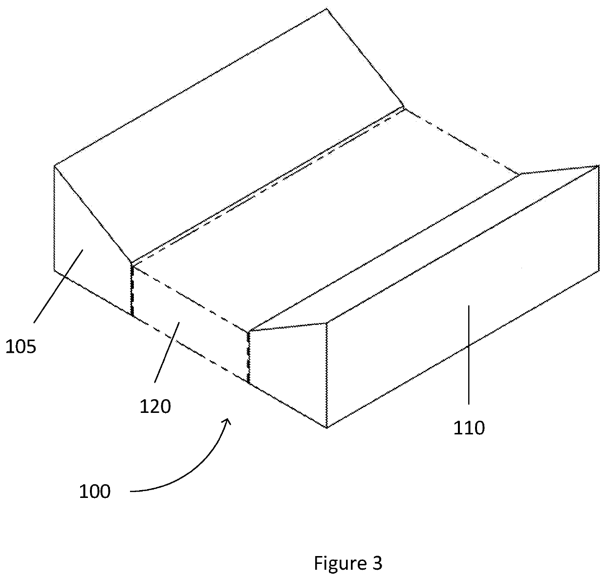
[0039]The technology described herein is directed towards a system or kit of magnets suitable for use in an external NMR system. In particular, in accordance with some embodiments, an efficiently designed, system or kit of magnets may be configured to produce a uniform magnetic field within a target region located inside a subject's body or internal organs to enable the NMR system to make in vivo measurements from the subject. Various embodiments provide a magnet system or kit that may enable measurement within large, non-planar bodies, such as a human torso. The system may include a backplane and multiple permanent magnets disposed thereon. In some examples, the magnets may be trapezoidal prism shaped magnets in a concave or V-shaped configuration to accommodate projection of a low-field magnetic field within a subject located adjacent to the system. Additionally, as a result of the concave or V-shaped configuration, the object of measurement may be surrounded by at least one magne...


PUM

PropertyMeasurementUnit
magnetic fieldaaaaaaaaaa
diameteraaaaaaaaaa
NMRaaaaaaaaaa

Abstract

A magnet system for use in a nuclear magnetic resonance (“NMR”) apparatus includes a first magnet and a second magnet located on a backplane to form a gap therebetween, wherein the first magnet and the second magnet are each shaped to form trapezoidal prisms with dimensions selected to optimize a magnetic field at a target region in space external to the magnet system.

Description

CROSS-REFERENCE TO RELATED APPLICATIONS[0001]This application claims the benefit of and priority to U.S. Provisional Application Ser. No. 62 / 756,689 filed Nov. 7, 2018, the contents of which are incorporated herein by reference.FIELD[0002]The disclosed technology relates generally to nuclear magnetic resonance (“NMR”) and magnetic resonance imaging (“MM”) devices, and more specifically to magnet systems for low-field NMR.BACKGROUND[0003]NMR and MRI are techniques used to measure, detect, survey, and / or understand patient health by imaging, detecting, and / or monitoring conditions and / or materials present internal to a biological subject, i.e., a human or animal patient. Generally, NMR and MM devices must generate high magnetic field strengths (in the order of 1.5 Tesla or greater) in order to reliably provide health data to a physician.[0004]The liver is the largest organ inside the human body. It helps the body digest food and prevents harmful toxins from entering the blood. Disease...

Claims


Application Information

Patent Timeline
Patent Type & Authority Applications(United States)
IPC IPC(8): H01F7/02
CPCH01F7/0278H01F7/021
Inventor LOWN, ROBERT R.
Owner LIVIVOS INC
Why Eureka
Try Eureka