Method and device for detecting blood pressure calibration time point

a blood pressure and calibration time technology, applied in the field of methods and devices for detecting blood pressure calibration time points, can solve the problems of not detecting a change in blood pressure, user cannot obtain a precise blood, and abrupt increase of blood pressur

Active Publication Date: 2020-05-14
SAMSUNG ELECTRONICS CO LTD
View PDF0 Cites 10 Cited by
  • Summary
  • Abstract
  • Description
  • Claims
  • Application Information

AI Technical Summary

Problems solved by technology

If the blood pressure calibration is not made, the user cannot obtain a precise blood pressure value in the cuff-less hemodynamometer, and thus may not detect a change of blood pressure, in particular, an abrupt increase of the blood pressure.
Accordingly, it may be difficult for the user to accurately recognize the blood pressure calibration time point of the user.
Currently, in the cuff-less hemodynamometer, the calibration time point is informed of to all the users based on the experimental results of the manufacturer that manufactured the cuff-less hemodynamometer, and the user may fail to calibrate the blood pressure at a necessary time point or may have to further perform an unnecessary calibration operation.
Moreover, because the cuff-less hemodynamometer has to be used each time in order to recognize a more precise blood pressure calibration time point, it may be difficult to achieve the purpose of use of the cuff-less hemodynamometer.
The user uses the cuff-less hemodynamometer to reduce disadvantages, such as inconveniences of the cuff hemodynamometer and inconveniences of movement of a device, and it may not be meaningful to use cuff-less hemodynamometer if the cuff hemodynamometer is frequently used to recognize a precise blood pressure correction time point.

Method used


Image

  • Method and device for detecting blood pressure calibration time point
  • Method and device for detecting blood pressure calibration time point
  • Method and device for detecting blood pressure calibration time point

Examples


Embodiment Construction

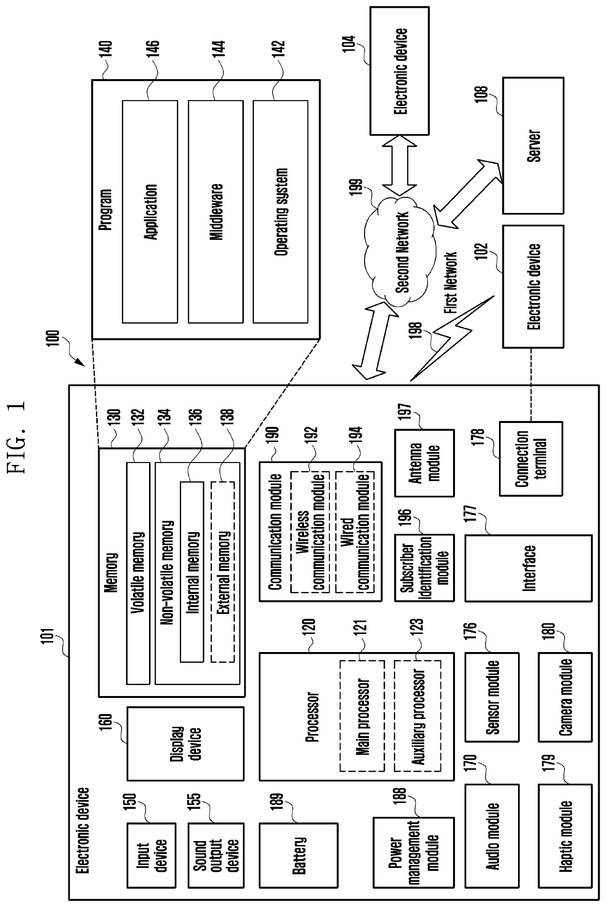
[0033]The electronic device according to various embodiments may be one of various types of electronic devices. The electronic devices may include, for example, and without limitation, a portable communication device (e.g., a smart phone), a computer device, a portable multimedia device, a portable medical device, a camera, a wearable device, a home appliance, or the like. According to an embodiment of the disclosure, the electronic devices are not limited to those described above.

[0034]It should be appreciated that various embodiments of the present disclosure and the terms used therein are not intended to limit the technological features set forth herein to particular embodiments and include various changes, equivalents, or replacements for a corresponding embodiment. With regard to the description of the drawings, similar reference numerals may be used to refer to similar or related elements. It is to be understood that a singular form of a noun corresponding to an item may inclu...


PUM


Abstract

An electronic device includes housing, a user interface disposed in a first part of the housing, a photoplethysmogram (PPG) sensor disposed to be exposed through a second part of the housing, the PPG sensor configured to calculate a blood pressure value while contacting a portion of a body, at least one sensor, a wireless communication circuit disposed in the interior of the housing, a processor disposed in the interior of the housing, and operatively connected to the user interface, the PPG sensor, the at least one sensor, and the wireless communication circuit, and a memory operatively connected to the processor, wherein the memory stores instructions that, when executed by the processor, control the electronic device to: receive first data from the at least one sensor, receive second data from the PPG sensor based at least in part on the received first data, determine a pulse arrival time (PAT) value, a heart rate (HR) value, and a pulse transit time (PTT) value from the second data, calculate a first blood pressure value (BP1) and a second blood pressure value (BP2) by applying the determined values to pulse wave velocity (PWV) algorithms of Equations 1 and 2, wherein BP1≅a1PAT+b1HR+c1 . . . Equation 1, BP2≅a2 ln(PTT)+b2 . . . Equation 2 in Equations 1 and 2, a1, a2, b1, b2, and c1 are constant values for matching blood pressure values measured during calibration with blood pressure values measured by a cuff hemodynamometer, determine a calibration time point based at least in part on a difference between the first blood pressure value and the second blood pressure value, and provide guide information related to the calibration time point through the user interface based at least in part on the determination.

Description

CROSS-REFERENCE TO RELATED APPLICATION[0001]This application is based on and claims priority under 35 U.S.C. § 119 to Korean Patent Application No. 10-2018-0138370, filed on Nov. 12, 2018, in the Korean Intellectual Property Office, the disclosure of which is incorporated by reference herein in its entirety.BACKGROUND1) Field[0002]The disclosure relates to a method and a device for detecting a blood pressure calibration time point.2) Description of Related Art[0003]As interests of the users in health have increased, various kinds of biometric information measuring devices have been developed. The methods for measuring biometric information may be largely classified into an invasive measurement method and a noninvasive measurement method. The noninvasive measurement methods, by which a pulse can be simply detected while pain is not caused to the user, have been widely used. For example, the noninvasive blood pressure measurement methods are methods for calculating a blood pressure wi...

Claims


Application Information

Patent Timeline
Patent Type & Authority Applications(United States)
IPC IPC(8): A61B5/0205A61B5/00A61B5/01A61B5/1171A61B5/11
CPCA61B5/02427A61B5/02055A61B5/681A61B5/1171A61B5/1118A61B5/4809A61B5/01A61B2560/0238A61B5/02125A61B5/721A61B5/0002A61B2562/0219A61B5/7475A61B5/021A61B5/7235A61B5/7275A61B5/02416A61B5/0024
Inventor LEE, DONGHYUNJUNG, SUNOKSHIN, SEUNGHWAN
Owner SAMSUNG ELECTRONICS CO LTD
Why Eureka
Try Eureka