Method for controlling dwell time during processing to optical component

Pending Publication Date: 2020-05-14
INST OF OPTICS & ELECTRONICS - CHINESE ACAD OF SCI
View PDF0 Cites 0 Cited by
  • Summary
  • Abstract
  • Description
  • Claims
  • Application Information

AI Technical Summary

Benefits of technology

The present invention provides a method for smoothing the dwell time during the processing of an optical component. The method can compensate for non-circularly symmetric removal functions and improve the convergence effect of the iterative calculation. Additionally, the method reduces the adverse effect on the stability of the machine tool due to frequent acceleration or deceleration of the polishing tool during processing, resulting in a reduction of surface shape errors introduced by the equipment during machining.

Problems solved by technology

However, in an actual high-precision machining, the amount of data and the amount of calculation involved in the calculation process are very large, which makes it difficult to obtain an overall optimal solution.
However, neither of the above methods takes a smoothing problem of the dwell time distribution into account; in a condition that the dwell time variation between each two adjacent discrete points is too large, that is, the dwell time distribution is not smoothing enough, it is likely that the polishing tool accelerates or decelerates frequently during the movement thereof, thereby adversely affecting the stability of the machine tool, and thus leaving a movement trail on the surface of the machined component.
Since the surface shape error is introduced during the processing to the processing equipment, and a correction to the medium frequency surface shape error and the high frequency surface shape error is a technical difficulty in the current numerical control processing, then they are difficult to be corrected by a secondary processing.

Method used


Image

  • Method for controlling dwell time during processing to optical component
  • Method for controlling dwell time during processing to optical component
  • Method for controlling dwell time during processing to optical component

Examples


embodiments

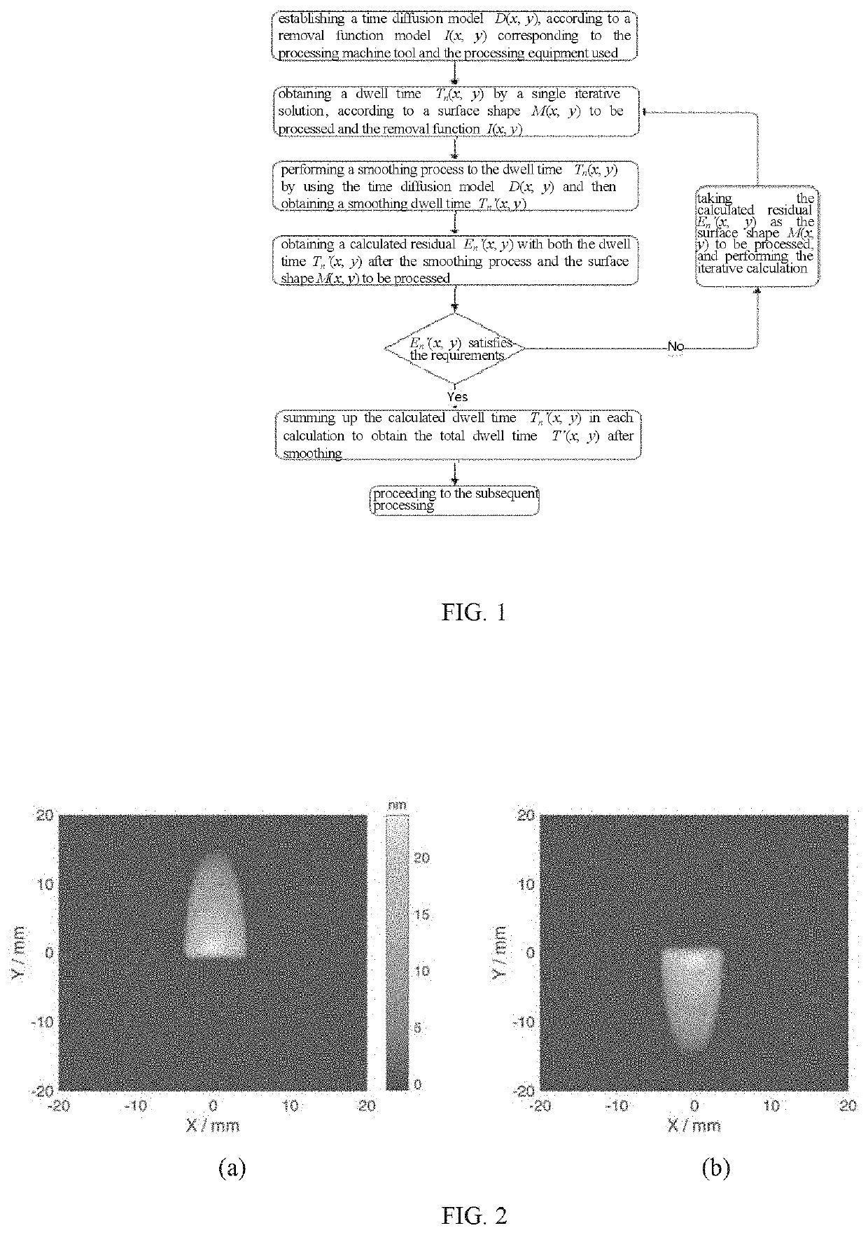
[0039]In this embodiment, a magnetorheological numerical control polishing machine is used as a processing device, and a circular flat mirror having a diameter of 100 mm is used as a component to be processed, and a specific embodiment of the present disclosure is exemplified in conjunction with FIG. 2 to FIG. 7. In the following description, the method for smoothing a dwell time during a processing to an optical component according to the present disclosure is simply referred to as a smoothing method. Under normal circumstances, the removal function of the magnetorheological polishing machine is non-circularly symmetric.

[0040]FIG. 2(a) shows the removal function distribution I(x, y) of the magnetorheological polishing head dwell at the coordinate point of x=0, y=0 for 3 seconds. In this embodiment, the shape distribution of the removal function distribution after being rotated by 180 degrees with respect to a coordinate point of x=0, y=0 may function as a time diffusion model D(x, ...


PUM

PropertyMeasurementUnit
Angleaaaaaaaaaa
Timeaaaaaaaaaa
Stabilityaaaaaaaaaa

Abstract

A method for smoothing a dwell time during a processing to an optical component belongs to the field of processing optical components, and solves a problem of an adverse effect of dwell time jumps on a stability of the machine tool during processing. The method achieves a smoothing treatment to the dwell time by a diffusion transformation to the distribution of the conventionally calculated dwell time using a time diffusion model. After the smoothing treatment to the dwell time, the difference between times at adjacent discrete points is relatively small, thereby achieving a smooth transition between adjacent discrete points, and limiting the effect of the polishing tool on machine stability due to its frequent acceleration and deceleration during processing.

Description

INCORPORATION BY REFERENCE TO ANY PRIORITY APPLICATIONS[0001]Any and all applications for which a foreign or domestic priority claim is identified in the Application Data Sheet as filed with the present application are hereby incorporated by reference.BACKGROUND OF THE INVENTIONField of the Invention[0002]The embodiment of the present disclosure relates to a method for smoothing a dwell time during a processing to an optical component, which belongs to a field of processing the optical component.Description of the Related Art[0003]With a rapid development of optical technology and a continuous expansion of its application range, people have put forward higher and higher requirements on technical indicators of the optical components, such as the surface shape precision and surface roughness. An aspherical surface, a relatively large caliber, and a nanometer-order precision become development trends of modern optical components. In order to effectively improve the surface processing q...

Claims


Application Information

Patent Timeline
IPC IPC(8): B24B49/02
CPCB24B49/02B24B1/00B24B13/00G06F17/153
Inventor HU, XIAOCHUANZHONG, XIANYUNLAI, ZHAOHUIYANG, JINSHAN
Owner INST OF OPTICS & ELECTRONICS - CHINESE ACAD OF SCI
Why Eureka
Try Eureka