Synthetic Apertures for Long-Range, Sub-Diffraction Limited Visible Imaging Using Fourier Ptychography

Active Publication Date: 2020-05-14
RICE UNIV +1
View PDF0 Cites 6 Cited by
  • Summary
  • Abstract
  • Description
  • Claims
  • Application Information

AI Technical Summary

Benefits of technology

[0013]The present application discloses a method for imaging objects using macroscopic Fourier ptychography (FP) as a practical means of creating a synthetic aperture for visible imaging to achieve sub-diffraction limited res

Problems solved by technology

In these scenarios, the imaging device is sufficiently far away from the object that imaging resolution is fundamentally limited not by magnification, but rather by the diffraction of light at the limiting aperture of the imaging system: using a lens with a larger aperture will lead to increased spatial resolution.
Physically increasing the aperture of the lens, by building a larger lens, re

Method used


Image

  • Synthetic Apertures for Long-Range, Sub-Diffraction Limited Visible Imaging Using Fourier Ptychography
  • Synthetic Apertures for Long-Range, Sub-Diffraction Limited Visible Imaging Using Fourier Ptychography
  • Synthetic Apertures for Long-Range, Sub-Diffraction Limited Visible Imaging Using Fourier Ptychography

Examples


Embodiment Construction

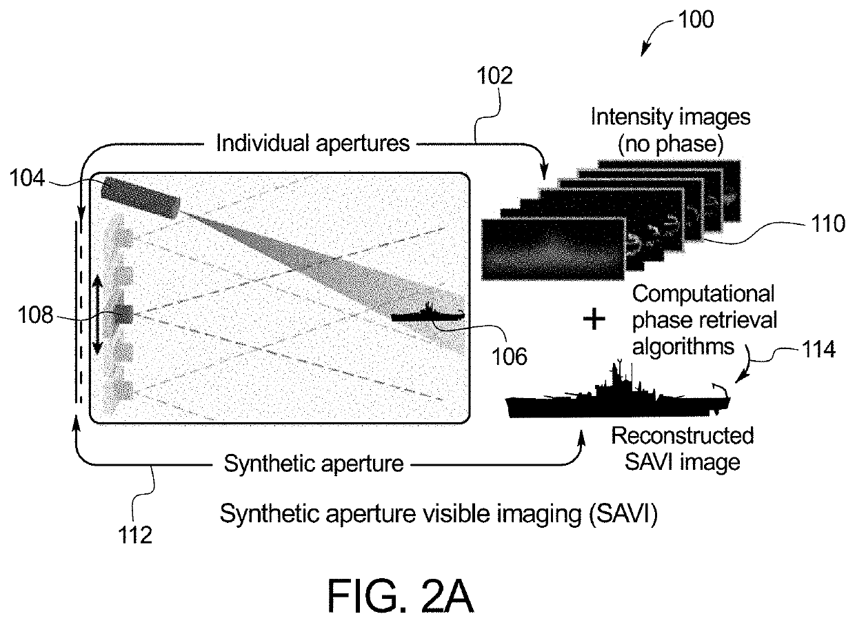
[0031]FIG. 2A is a diagram illustrating a synthetic aperture for visible imaging (SAVI) technique 100. In a first step 102, a coherent source 104, e.g. a laser, illuminates a distant target 106 and the reflected signal is captured by a camera system 108 in intensity images 110. The camera system 108 is translated to capture all of the light that would enter the desired synthetic aperture in a second step 112. Unlike SAR, phase information cannot be recorded for visible light. High-resolution image reconstruction therefore necessitates post-capture computational phase recovery in a third step 114.

[0032]FIG. 2B illustrates a further diagram of SAVI 200 in three steps. In the first step 202, a diffuse object 204 is illuminated with a coherent source 206 and overlapping images 208 are captured. Each image is low-resolution and suffers from speckle. In step 210, missing phase information is recovered computationally, which requires redundancy between captured intensity images. In step 21...


PUM


Abstract

A method for imaging objects includes illuminating an object with a light source of an imaging device, and receiving an illumination field reflected by the object. An aperture field that intercepts a pupil of the imaging device is an optical propagation of the illumination field at an aperture plane. The method includes receiving a portion of the aperture field onto a camera sensor, and receiving a sensor field of optical intensity. The method also includes iteratively centering the camera focus along the Fourier plane at different locations to produce a series of sensor fields and stitching together the sensor fields in the Fourier domain to generate an image. The method also includes determining a plurality of phase information for each sensor field in the series of sensor fields, applying the plurality of phase information to the image, receiving a plurality of illumination fields reflected by the object, and denoising the intensity of plurality of illumination fields using Fourier ptychography.

Description

CROSS-REFERENCE TO RELATED APPLICATIONS[0001]This application incorporates by reference and claims the benefit of priority to U.S. Provisional Patent Application No. 62 / 532,637 filed Jul. 14, 2017.STATEMENT REGARDING FEDERALLY SPONSORED RESEARCH OR DEVELOPMENT[0002]This invention was made with government support under CCF1117939, CCF1527501, CNS1338099, IIS1116718, and IIS1453192 awarded by the National Science Foundation; and HR0011-16-C-0028 awarded by the Defense Advanced Research Projects Agency (DARPA); N00014-14-1-0741 (Subcontract GG010550 from Columbia University) and N00014-15-1-2735 awarded by the Office of Naval Research. The government has certain rights in the invention.BACKGROUND OF THE INVENTION[0003]The present subject matter relates generally to synthetic apertures for visible imaging. More specifically, the present invention relates to synthetic apertures for visible imaging as a promising approach to achieve sub-diffraction resolution in long distance imaging.[000...

Claims


Application Information

Patent Timeline
IPC IPC(8): G01S13/90G02B27/58G02B21/00H04N5/235
CPCH04N5/217H04N1/3216H04N5/357H04N5/213H04N23/951H04N25/60H04N23/81
Inventor COSSAIRT, OLIVERHOLLOWAY, JASONVEERARAGHAVAN, ASHOKSHARMA, MANOJ KUMARWU, YICHENG
Owner RICE UNIV
Why Eureka
Try Eureka