
Exhaust after-treatment system with adjustable flow path, and method for operating such an exhaust after-treatment system

Active Publication Date: 2020-05-28
VOLVO LASTVAGNAR AB
View PDF0 Cites 2 Cited by
  • Summary
  • Abstract
  • Description
  • Claims
  • Application Information

AI Technical Summary

Benefits of technology

The present invention relates to an improved design for exhaust after-treatment systems (EATS) that can better mitigate emissions during low temperature and high temperature operations. Specifically, the invention addresses issues related to the current EATS which often struggle to efficiently convert NOx during cold operation and may release stored NOx before the conversion catalyst reaches its operating temperature, leading to higher emissions during the warm-up phase. The invention provides a solution that can facilitate faster warming up of EATS components, while also minimizing damage to components and facilitating the regeneration of storage catalysts. Overall, the invention improves the performance of EATS and enhances their ability to meet future emission standards.

Problems solved by technology

Anticipated increased stringency in engine and vehicle emission standards presents a new and unique problem for diesel after-treatment of exhaust gases.
Current combinations of storage and conversion catalysts are at risk of releasing the NOx stored in NOx traps or absorbers before the conversion catalyst reaches its operating temperature.
This allows for the passage of a spike of emissions during the warm up phase when temperatures are in a range in which the storage catalyst(s) releases NOx at but the conversion catalyst(s) are not yet efficiently converting the NOx.
A drawback to this arrangement is that exhaust gases are cooled by, among other things, the storage catalyst before they reach the conversion catalyst, leading to longer warm-up times for the conversion catalyst.
Extended exposure to higher temperatures can, however, damage the storage catalyst.

Method used


Image

  • Exhaust after-treatment system with adjustable flow path, and method for operating such an exhaust after-treatment system

Examples


Embodiment Construction

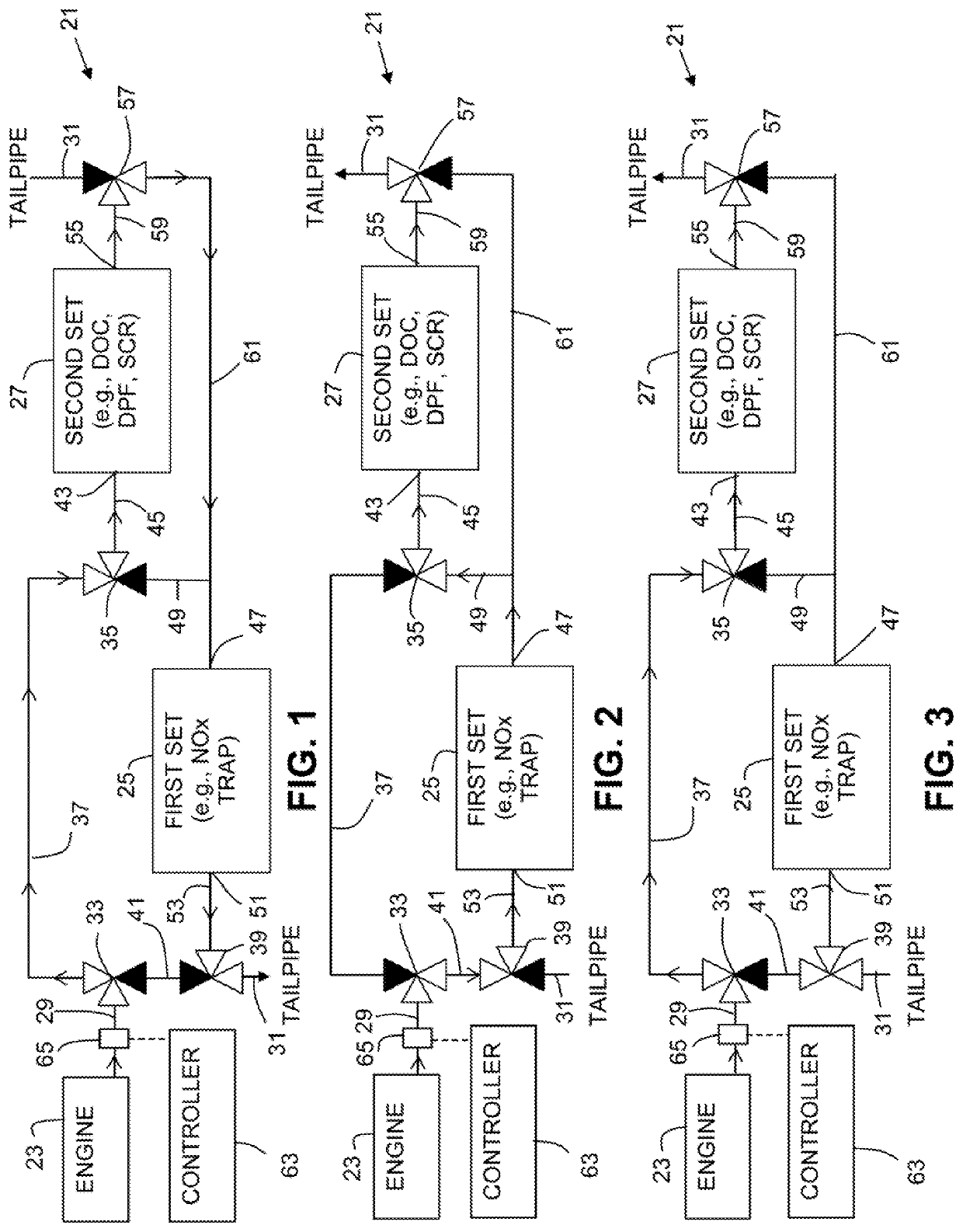
[0017]An exhaust after-treatment system 21 (EATS) for an engine 23 is schematically shown in different operating modes in FIGS. 1, 2, and 3. The technology discussed in the present application involves a diesel engine and associated EATS components, however, it will be appreciated that the present invention has application in other engine exhaust after-treatment systems.

[0018]The EATS 21 includes a first set of exhaust after-treatment components 25, a second set of exhaust after-treatment components 27, an inlet 29 to the exhaust after-treatment system such as a conduit connected to the exhaust manifold (not shown) of the engine, and an outlet or tailpipe 31 from the exhaust after-treatment system.

[0019]The EATS 21 further includes a valve and conduit arrangement configurable in a plurality of modes such that, in a first mode shown in FIG. 1, exhaust gas entering the inlet 29 flows through the second set of exhaust after-treatment components 27, then through the first set of exhaust...


PUM


Abstract

An exhaust after-treatment system includes a first set of exhaust after-treatment components, a second set of exhaust after-treatment components, an inlet to the exhaust after-treatment system, an outlet from the exhaust after-treatment system, and a valve and conduit arrangement configurable in a plurality of modes, in a first mode, exhaust gas entering the inlet flows through the second set of exhaust after-treatment components, then through the first set of exhaust after-treatment components, and then through the outlet. In a second mode, exhaust gas entering the inlet flows through the second set of exhaust after-treatment components without flowing through the first set of exhaust after-treatment components, and then through the outlet in a third mode, exhaust gas entering the inlet flows through the first set of exhaust after-treatment components, then through the second set of exhaust after-treatment components, and then through the outlet.

Description

BACKGROUND AND SUMMARY[0001]The present invention relates generally to exhaust after-treatment systems and methods for operating such systems.[0002]Anticipated increased stringency in engine and vehicle emission standards presents a new and unique problem for diesel after-treatment of exhaust gases. Engine emissions during low temperature operation will have to be mitigated better in order to meet the future emission standards. Current exhaust after-treatment systems (EATS) typically need to be at a warm temperature to get reasonable catalytic conversion of emissions. A NOx trap or absorber can be used to store NOx during cold operation. As exhaust temperature heats up, the NOx trap or absorber receives exhaust heat and releases stored NOx, typically to a NOx conversion catalyst, once that NOx conversion catalyst has reached its operating temperature. Current combinations of storage and conversion catalysts are at risk of releasing the NOx stored in NOx traps or absorbers before the...

Claims


Application Information

Patent Timeline
IPC IPC(8): F01N9/00F01N3/021F01N3/20F01N3/28F01N13/00F01N11/00
CPCF01N9/002F01N2900/1602F01N3/2892F01N13/011F01N11/002F01N3/021F01N3/2066F01N13/009F01N3/08F01N3/033F01N3/0814F01N3/0835F01N3/0842F01N3/103F01N2410/02F01N2410/03F01N2410/04F01N2560/06B01D53/9477B01D53/9481B01D2258/012B01D53/9418B01D53/9422B01D53/944Y02T10/12F01N9/00F01N2900/0422F01N2240/36F01N2590/08Y02T10/40
Inventor GEYER, STEPHEN
Owner VOLVO LASTVAGNAR AB
Features
  • Generate Ideas
  • Intellectual Property
  • Life Sciences
  • Materials
  • Tech Scout
  • Unparalleled Data Quality
  • Higher Quality Content
  • 60% Fewer Hallucinations
Learn More