System and method for optimizing combustion of boiler

a technology of optimizing combustion and boiler, applied in the direction of boiler control, combustion regulation, instruments, etc., can solve the problems of insufficient implementation of the optimal combustion environment of the boiler, and achieve the reduction of the cost of treating the emissions, the reduction of the optimum combustion environment of the boiler, and the improvement of the combustion efficiency of the boiler in the power plant.

Active Publication Date: 2020-06-04
DOOSAN HEAVY IND & CONSTR CO LTD
View PDF0 Cites 3 Cited by
  • Summary
  • Abstract
  • Description
  • Claims
  • Application Information

AI Technical Summary

Benefits of technology

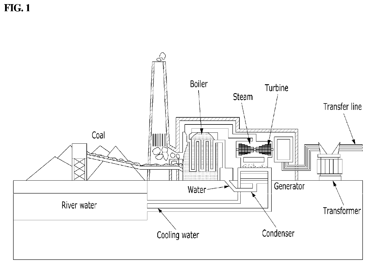
[0006]Aspects of one or more exemplary embodiments provide a system and method for controlling a boiler in a power plant to calculate an optimum set point for a control object in the boiler to maximize the combustion efficiency of the boiler while minimizing the generation of emissions including nitrogen oxides and carbon oxides.
[0030]According to one or more exemplary embodiments, the combustion efficiency of the boiler in a power plant can be improved and the emissions causing environmental pollution can also be minimized, whereby the cost of treating the emissions can be significantly reduced, thereby significantly reducing the operating cost of the power plant.
[0031]In addition, one or more exemplary embodiments can control the boiler in an optimized combustion state with reference to the results learned by artificial intelligence, so that even unskilled workers can realize, without difficulty, a better combustion environment compared to what is obtained by a skilled expert in the related art.

Problems solved by technology

Therefore, according to the related art boiler operating method, because it is not easy to control the boiler in an optimum combustion state when the boiler is operating, stable combustion control for the stability of the boiler has been given more priority than the optimum control thereof.
There has been a problem in the related art that the optimum combustion environment of a boiler could not be properly implemented.

Method used


Image

  • System and method for optimizing combustion of boiler
  • System and method for optimizing combustion of boiler
  • System and method for optimizing combustion of boiler

Examples


Embodiment Construction

[0037]Various modifications may be made to the embodiments of the disclosure, and there may be various types of embodiments. Thus, specific embodiments will be illustrated in drawings, and embodiments will be described in detail in the description. However, it should be noted that the various embodiments are not for limiting the scope of the disclosure to a specific embodiment, but they should be interpreted to include all modifications, equivalents or alternatives of the embodiments included in the ideas and the technical scopes disclosed herein. Meanwhile, in case it is determined that in describing the embodiments, detailed explanation of related known technologies may unnecessarily confuse the gist of the disclosure, the detailed explanation will be omitted.

[0038]Unless otherwise defined, the terms including technical and scientific terms used herein have the same meaning as would be generally understood by those skilled in the relevant art. However, these terms may vary dependi...


PUM


Abstract

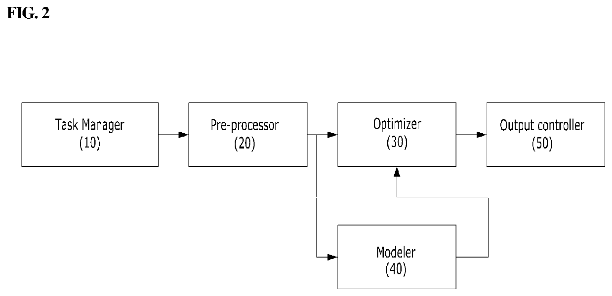
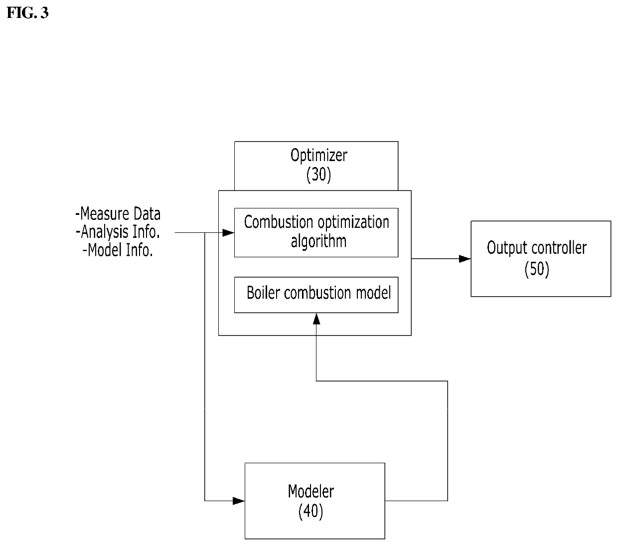
A system for controlling a boiler apparatus in a power plant to combust under optimized conditions, and a method for optimizing combustion of the boiler apparatus using the same are provided. The boiler control system may include a modeler configured to create a boiler combustion model, an optimizer configured to receive the boiler combustion model from the modeler and perform the combustion optimization operation for the boiler using the boiler combustion model to calculate an optimum control value, and an output controller configured to receive the optimum control value from the optimizer, and control an operation of the boiler by reflecting the optimum control value to a boiler control logic.

Description

CROSS REFERENCE TO RELATED APPLICATION[0001]This application claims priority to Korean Patent Application No. 10-2018-0152751, filed on Nov. 30, 2018, the entire disclosure of which is incorporated herein by reference in its entirety.BACKGROUND1. Field[0002]Apparatuses and methods consistent with exemplary embodiments relate to a system for controlling a boiler apparatus in a power plant to ensure combust under optimized conditions, and a method for optimizing combustion of the boiler apparatus using the same and, more particularly to a system and method for calculating an optimum control value or a set point for optimizing combustion of a boiler.2. Description of the Related Art[0003]A thermal power plant has a boiler therein to heat water by using an exothermic reaction generated when burning fuel such as coal or the like, thereby producing steam for driving a turbine. When a combustion occurs in the boiler, emissions such as nitrogen oxides and carbon dioxide are generated. In re...

Claims


Application Information

Patent Timeline
Patent Type & Authority Applications(United States)
IPC IPC(8): F22B35/18G05B13/04
CPCG05B13/042F22B35/18F23N5/265F23N2223/10F23N2225/04F23N2225/08F23N2223/40
Inventor MAENG, JWA YOUNGNA, SANG GUN
Owner DOOSAN HEAVY IND & CONSTR CO LTD
Why Eureka
Try Eureka