Temperature abnormality detection method for power conversion apparatus, and temperature abnormality detection device for power conversion apparatus

Active Publication Date: 2020-06-11
NISSAN MOTOR CO LTD
View PDF5 Cites 2 Cited by
  • Summary
  • Abstract
  • Description
  • Claims
  • Application Information

AI Technical Summary

Benefits of technology

[0007]In the temperature abnormality detection method for a power conversion apparatus of the present invention it is not necessary to detect the temperature of the cooling fluid upstream from the power converter of the subsequen

Problems solved by technology

However, if the prior art described above is applied to each power conversion apparatus, it becomes necessary to provide a cooling flow path in each power conversion apparatus, and to detect the temperatures of each of the power conver

Method used


Image

  • Temperature abnormality detection method for power conversion apparatus, and temperature abnormality detection device for power conversion apparatus
  • Temperature abnormality detection method for power conversion apparatus, and temperature abnormality detection device for power conversion apparatus
  • Temperature abnormality detection method for power conversion apparatus, and temperature abnormality detection device for power conversion apparatus

Examples


Example

First Embodiment

[0015]A temperature abnormality detection method and a power conversion apparatus for a power conversion apparatus of the first embodiment will be described below.

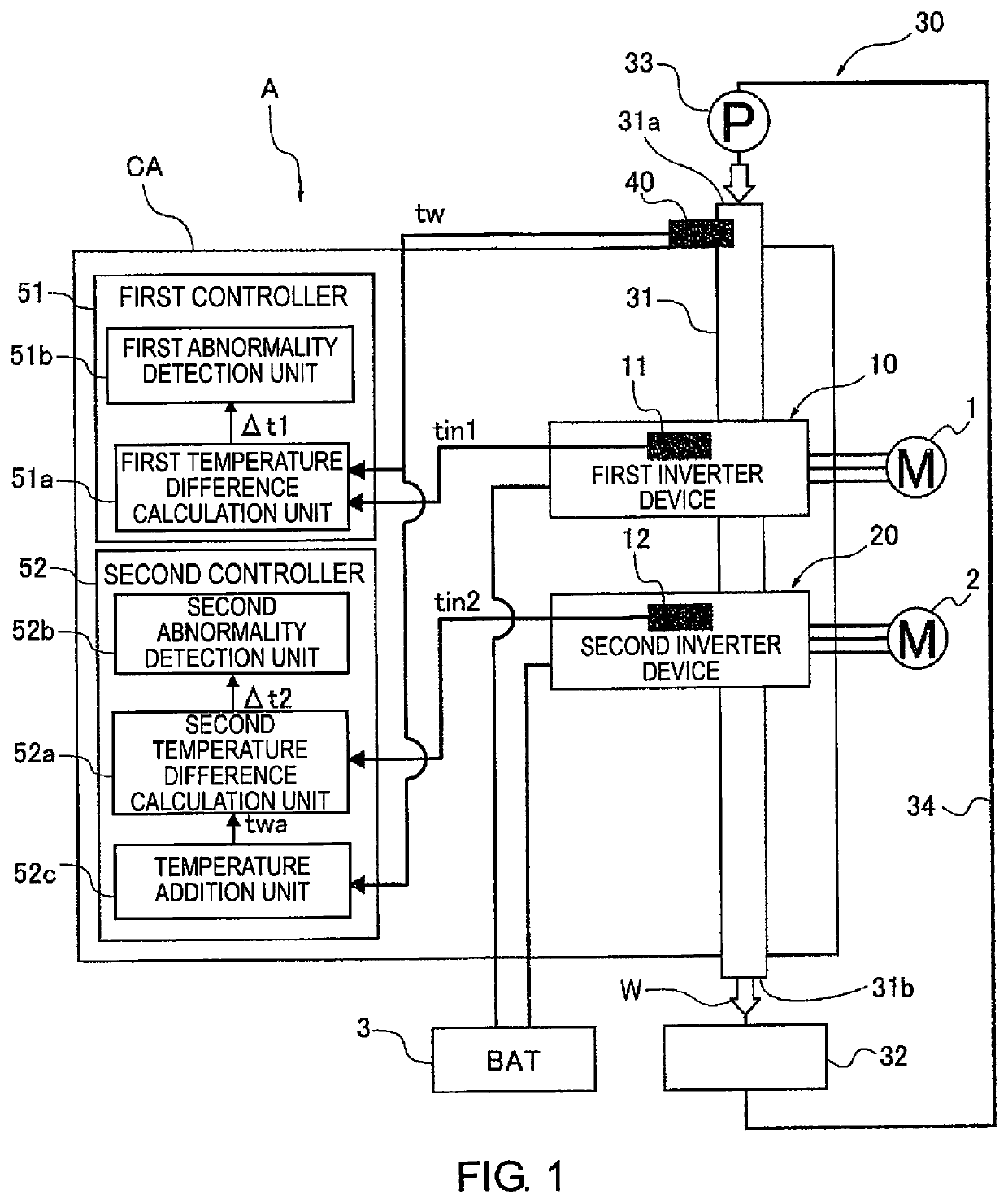
[0016]First, the configuration of a power conversion apparatus A to which the temperature abnormality detection method according to the first embodiment is applied will be described with reference to FIG. 1.

[0017]The power conversion apparatus A illustrated in FIG. 1 comprises a first inverter device (a power converter) 10 for driving a first power generation machine 1, and a second inverter device (a power converter) 20 for driving a second power generation machine 2.

[0018]The first power generation machine 1 and the second power generation machine 2 are mounted in an electric vehicle, a hybrid vehicle, or the like, which is not shown. The purposes of the two power generation machines 1, 2 are not particularly limited. For example, the two power generation machines 1, 2 can be used as drive sources for sup...

Example

Second Embodiment

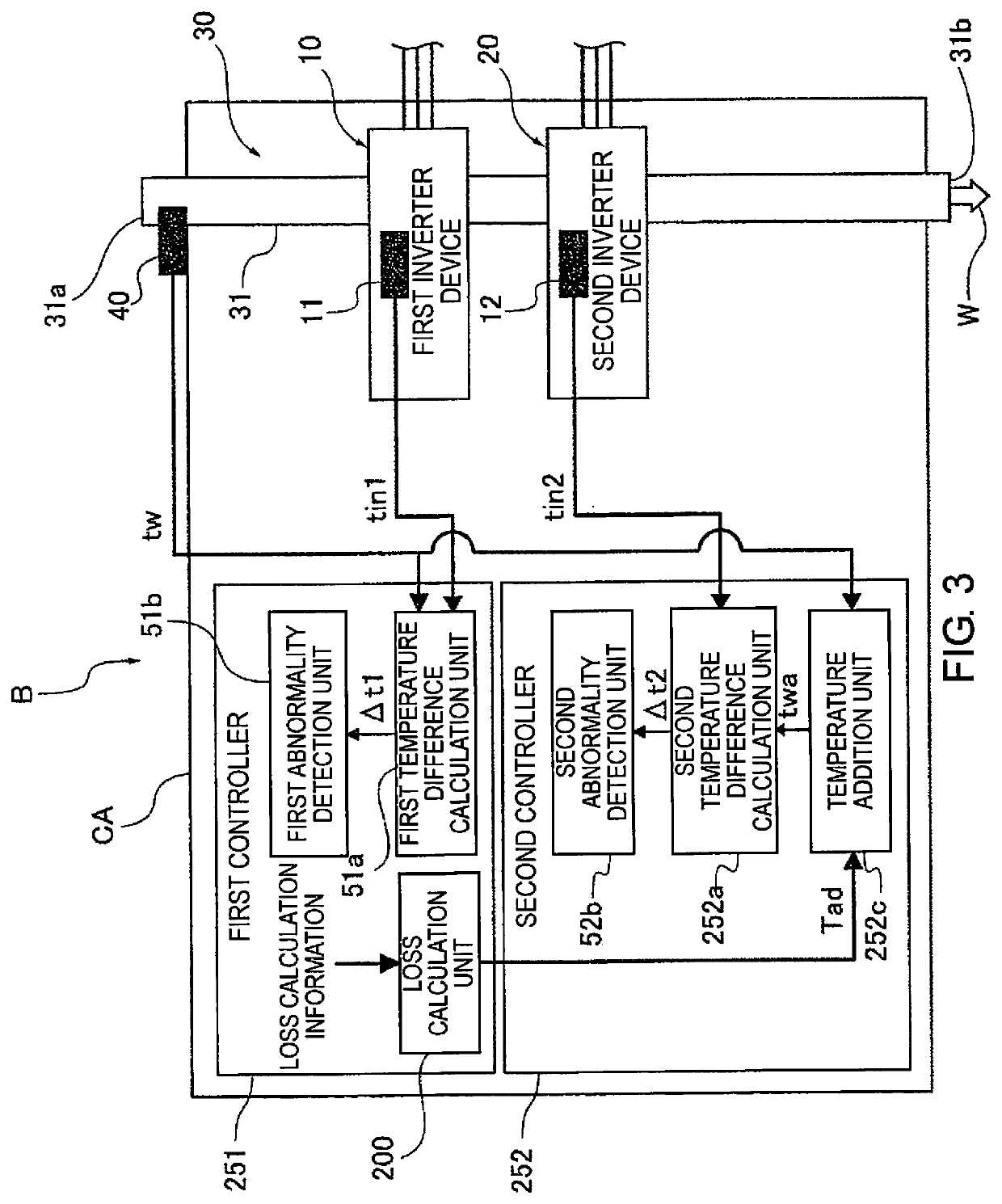
[0058]The second embodiment is an example in which the method of converting the loss component of the first inverter device 10 into temperature and adding the same to the cooling water temperature tw is different from that of the first embodiment. That is, in the second embodiment, a value calculated based on loss calculation information that includes semiconductor characteristics, the carrier frequency, and the current supplied to the first inverter device 10, is used as the temperature obtained by converting the loss component of the first inverter device 10.

[0059]FIG. 3 is an overall view schematically illustrating a power conversion apparatus B to which the temperature abnormality detection method of the second embodiment is applied. In the temperature addition unit 252c of the second controller 252 illustrated in FIG. 3, an addition value calculated by a loss calculation unit 200 provided in the first controller 251 is used as the addition value, which is the t...

Example

Third Embodiment

[0075]The third embodiment is an example in which the method of converting the loss component of the first inverter device 10 into temperature and adding the same to the cooling water temperature tw to obtain the addition value Tad is different from those of the first and second embodiments.

[0076]That is, in the third embodiment, a value estimated based on the first temperature difference Δt1 between the temperature of the first inverter device 10 and the cooling water temperature tw is used as the addition value Tad that is added after the loss component of the first inverter device 10 is converted to temperature.

[0077]FIG. 4 is an overall view schematically illustrating a power conversion apparatus C to which the temperature abnormality detection method of the third embodiment is applied. The second temperature difference calculation unit 352a of the second controller 352 shown in FIG. 4 calculates a second temperature difference Δt2 between the added temperature t...


PUM


Abstract

A temperature abnormality detection method for a power conversion apparatus basically includes a detecting a first power converter temperature, a second power converter temperature and a cooling water temperature and then determining a presence of an abnormality in a preceding stage power converter based on a first temperature difference between the first power converter temperature and the cooling water temperature. The abnormality detection method further includes determining a presence of an abnormality in a subsequent stage power converter based on a second temperature difference between the second power converter temperature and an added temperature that is obtained by adding to the loss component of the preceding stage power converter converted to a temperature to the cooling water temperature.

Description

CROSS-REFERENCE TO RELATED APPLICATIONS[0001]This application is a U.S. national stage application of International Application No. PCT / JP2016 / 065728, filed on May 27, 2016.BACKGROUNDField of the Invention[0002]The present invention relates to a temperature abnormality detection method for a power conversion apparatus and a temperature abnormality detection device for a power conversion apparatus.Background Information[0003]Conventionally, a technique is known in which a cooling flow path for circulating cooling water is provided in a power conversion apparatus such as an inverter device to protect the device from overheating, and temperature abnormalities are detected in the power conversion apparatus or the cooling flow path (for example, see Japanese Laid Open Patent Application No. 2011-172406—Patent Document 1). In this prior art the difference between the temperature of the cooling water and the temperature of the power conversion apparatus is compared with a temperature thres...

Claims


Application Information

Patent Timeline
IPC IPC(8): G01K3/08H01L23/473H02M1/32H02M7/5395H05K7/20
CPCH02P5/74H01L23/473G01K3/08H02M7/5395H02M1/32H05K7/20927H02M2001/327H02M7/48G01K7/42H02M1/327G01R31/40
Inventor MARUYAMA, SHO
Owner NISSAN MOTOR CO LTD
Why Eureka
Try Eureka