Heat exchanger with multistaged cooling

a heat exchanger and multi-stage technology, applied in the direction of sustainable manufacturing/processing, separation processes, final product manufacturing, etc., can solve the problems of inefficiency, large volume of existing solutions in the art, and inability to recombine and cool the effluen

Active Publication Date: 2020-06-18
APPLIED MATERIALS INC
View PDF0 Cites 4 Cited by
  • Summary
  • Abstract
  • Description
  • Claims
  • Application Information

AI Technical Summary

Benefits of technology

[0009]One or more embodiments described herein also generally relate to methods of forming a heat exchanger.
[0010]In one embodiment, a method of forming a heat exchanger that is configured to exchange heat with a flowing fluid includes forming a first mounting flange having a central opening. Forming the first mounting flange comprises sequentially depositing layers of a thermally conductive material on a first surface. A heat exchanging body is formed on the first mounting flange, wherein the heat exchanging body has a heat exchanging section that encloses a heat exchanging region that extends in a direction that is perpendicular to the first surface. Forming the heat exchanging body comprises sequentially depositing layers of the thermally conductive material on a surface of the formed first mounting flange. The sequentially deposited layers disposed within the heat exchanging section each include at least a portion of an outer wall ...

Problems solved by technology

However, abatement of certain compounds using water vapor in the remote plasma source can result in the formation of solid particles in the remote plasma source due to lower combination reaction time available and equipment downstream of the remote plasma source, such as exhaust lines and pumps.
In addition...

Method used


Image

  • Heat exchanger with multistaged cooling
  • Heat exchanger with multistaged cooling
  • Heat exchanger with multistaged cooling

Examples


Embodiment Construction

[0024]In the following description, numerous specific details are set forth to provide a more thorough understanding of the embodiments of the present disclosure. However, it will be apparent to one of skill in the art that one or more of the embodiments of the present disclosure may be practiced without one or more of these specific details. In other instances, well-known features have not been described in order to avoid obscuring one or more of the embodiments of the present disclosure.

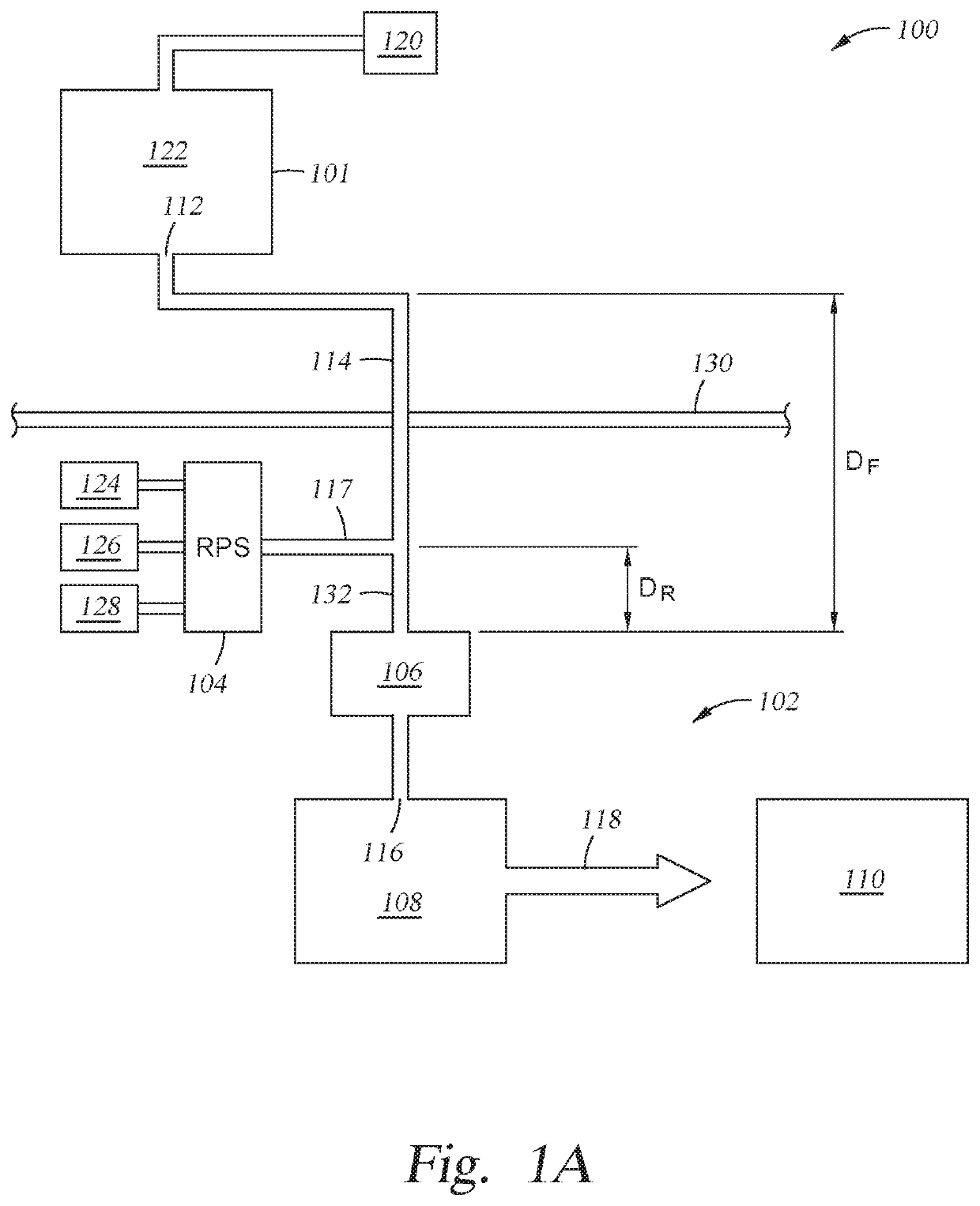
[0025]Embodiments described herein generally relate to an abatement system and a heat exchanger for removing unwanted compounds produced in semiconductor processes from the effluent stream. After leaving a plasma zone and entering the heat exchanger, a fluid and a solid effluent recombines and releases a significant amount of energy, leading to a temperature increase of the already hot effluent. To counteract the temperature increase, a cooling mechanism is designed into the heat exchanger. The coo...


PUM

PropertyMeasurementUnit
Angleaaaaaaaaaa
Diameteraaaaaaaaaa
Diameteraaaaaaaaaa

Abstract

Embodiments described herein relate to a heat exchanger for abating compounds produced in semiconductor processes. When hot effluent flows into the heat exchanger, a coolant can be flowed to walls of a fluid heat exchanging surface within the heat exchanger. The heat exchanging surface can include a plurality of channel regions which creates a multi stage cross flow path for the hot effluent to flow down the heat exchanger. This flow path forces the hot effluent to hit the cold walls of the fluid heat exchanging surface, significantly cooling the effluent and preventing it from flowing directly into the vacuum pumps and causing heat damage. Embodiments described herein also relate to methods of forming a heat exchanger. The heat exchanger can be created by sequentially depositing layers of thermally conductive material on surfaces using 3-D printing, creating a much smaller footprint and reducing costs.

Description

CROSS-REFERENCE TO RELATED APPLICATIONS[0001]This application claims priority to U.S. Provisional Patent Application No. 62 / 779,385, filed Dec. 13, 2018, which is herein incorporated by reference in its entirety.BACKGROUNDField[0002]Embodiments described herein generally relate to semiconductor processing equipment and, more particularly, to an abatement system and a heat exchanger for abating compounds produced in semiconductor processes.Description of the Related Art[0003]Process gases used by semiconductor processing facilities include many compounds, such as perfluorocarbons (PFCs), which must be abated or treated before disposal, due to regulatory requirements and environmental and safety concerns. Typically, a remote plasma source may be coupled to a processing chamber to abate the compounds coming out of the processing chamber. A reagent may be injected into the plasma source to assist the abatement of the compounds.[0004]Conventional abatement technology for abating PFCs uti...

Claims


Application Information

Patent Timeline
IPC IPC(8): F28D1/02F28F9/00
CPCF28D2001/0266F28D2001/0273F28F9/002F28D1/0246F28D7/005F28D7/0058F28D7/0075F28D7/08F28D9/04F28D2021/0075B01D5/0003B01D5/0045H01J37/32844H01J37/32834H01L21/67017Y02P70/50
Inventor GAJENDRA, MANOJ A.
Owner APPLIED MATERIALS INC
Why Eureka
Try Eureka